
Solar farm layers: how GenAnywhere shows the arrays
The panel holds ground, cover and buildings; the tables and trackers are placed over that site rather than generated with it.
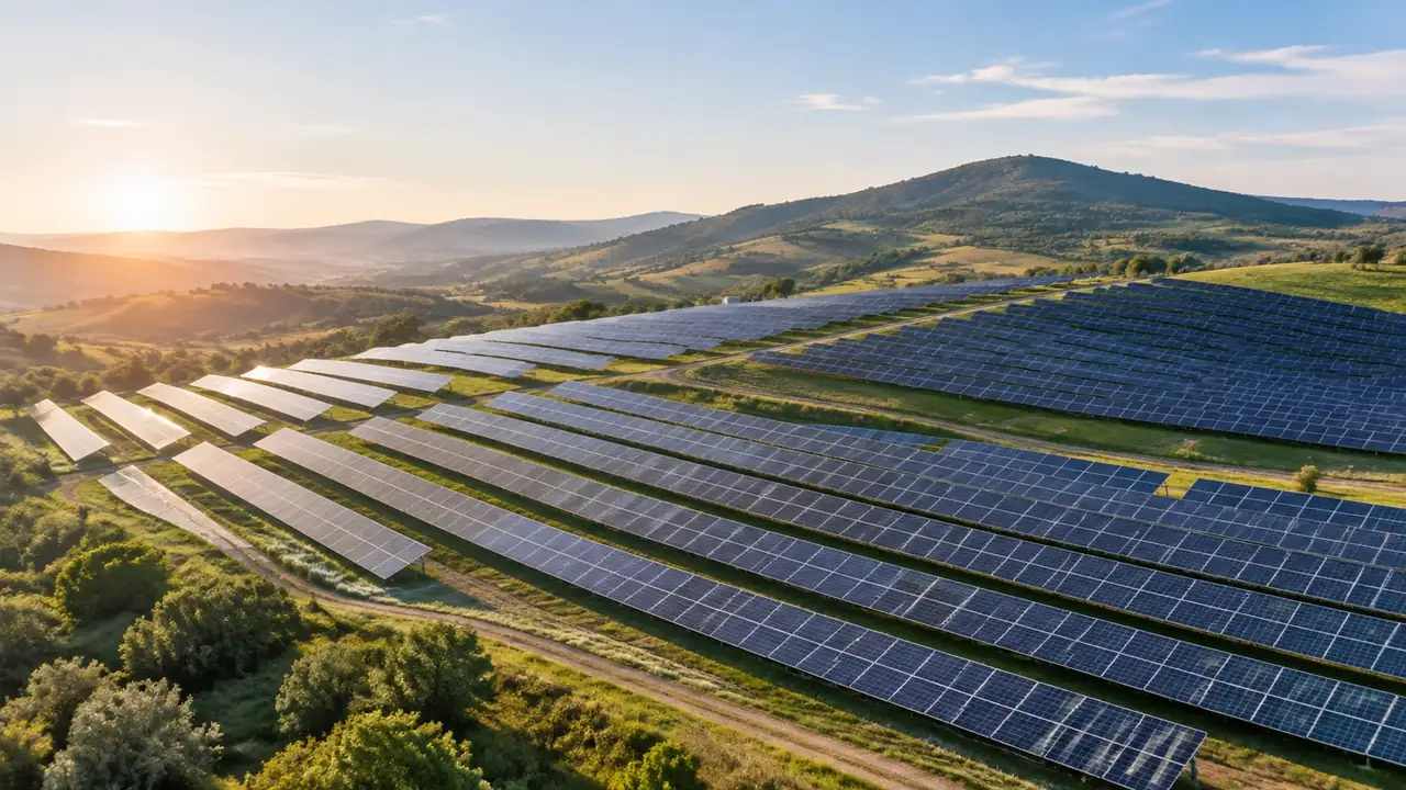
GenAnywhere shows a solar plant through three layers, and none of them is the array. The panel carries terrain, vegetation and buildings. Tables, trackers and inverter stations are design assets placed over that ground. For a layout discussion the split is workable, because rows, setbacks and compounds are decided against the ground and against what already grows on it, and those two things are what the layers describe.
1 What the panel holds at a plant
1.1 Terrain, vegetation and buildings
Terrain carries the ground surface and any water inside the boundary, which at a plant means slope, a drainage line and the occasional pond. Vegetation carries hedges, shelter belts and scrub that the analysis can see. Buildings carries the O and M store, the site office and any farm sheds left in the field. Each row toggles on its own. On a flat field with one compound the buildings row is short, and it still answers where that compound sits. Grass and crops read as cover rather than as surface, so the ground under them is inferred rather than measured.
1.2 Why arrays are not in the panel
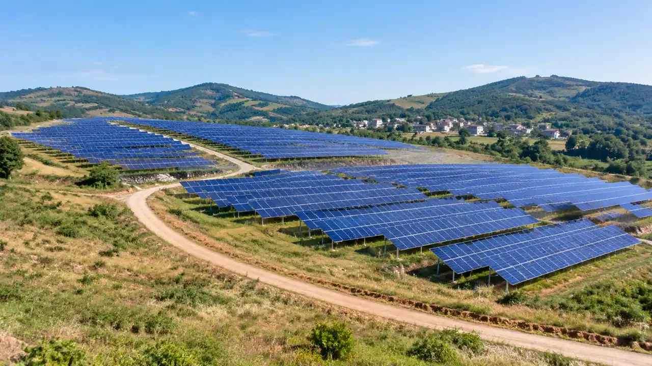
Array rows are long, thin and repeated, and nothing in a map capture lets a platform infer them as generated content with any confidence. Table dimensions, pitch, tracker type and capacity come from the layout design. Placing array geometry is a design act, and it sits above the terrain as an overlay the layer controls do not touch. Teams hunting for an array toggle are looking in the wrong panel. That is not a gap in the tool so much as a line between site and plant.
2 Terrain and the row layout
2.1 Slope and earthworks
Rows follow contours, and a scene with vegetation off shows those contours plainly. A field that looks flat on a plan often has a fall across it that changes how tables are set out, and the terrain layer makes that fall visible before a grading plan exists. The platform does not design earthworks or balance cut and fill. What it does is open the conversation about which parts of the field will need work and which will not. Walk the fall in two directions before the review, because a single camera angle flattens it.
2.2 Setbacks, tracks and the boundary
The boundary is a land question, and terrain plus buildings shows what sits inside it and what sits just outside. A hedge line, a ditch, a neighbour's barn: each is visible in one layer state or another. Access tracks are not generated by the platform, so they are drawn in the layout tool and checked against the scene afterwards. Use the view to agree where the fence runs and what has to stay clear of it, then take the track design elsewhere. Where a footpath crosses the site, the boundary argument gets harder and the layer view helps less.
3 Vegetation as screening and constraint
3.1 Existing cover inside the fence
Grassland, scrub and young woodland read differently in the vegetation layer, and each implies a different clearing effort. On former industrial land, scrub can hide rubble and level changes that matter more than the plants themselves. Switching buildings off makes the cover pattern easier to follow. Where the site is pasture the layer is thin and the terrain does most of the talking, which is useful to know before the meeting rather than halfway through it. Aerial capture also shows tracks made by farm vehicles, which often mark ground that drains badly.
3.2 Neighbours and visual screening
A plant at the edge of a village is judged partly on what can be seen from the road, and vegetation is what screens it. The layer shows the belt that exists, not one that is proposed, and it does not model growth or seasonal leaf cover. Note both when a screening argument comes up, because a winter capture can be a poor guide to July. Proposed planting belongs in the landscape design, with species and maintenance decided by people who will be held to them.
4 Buildings, compounds and the rest
4.1 The substation and O and M buildings
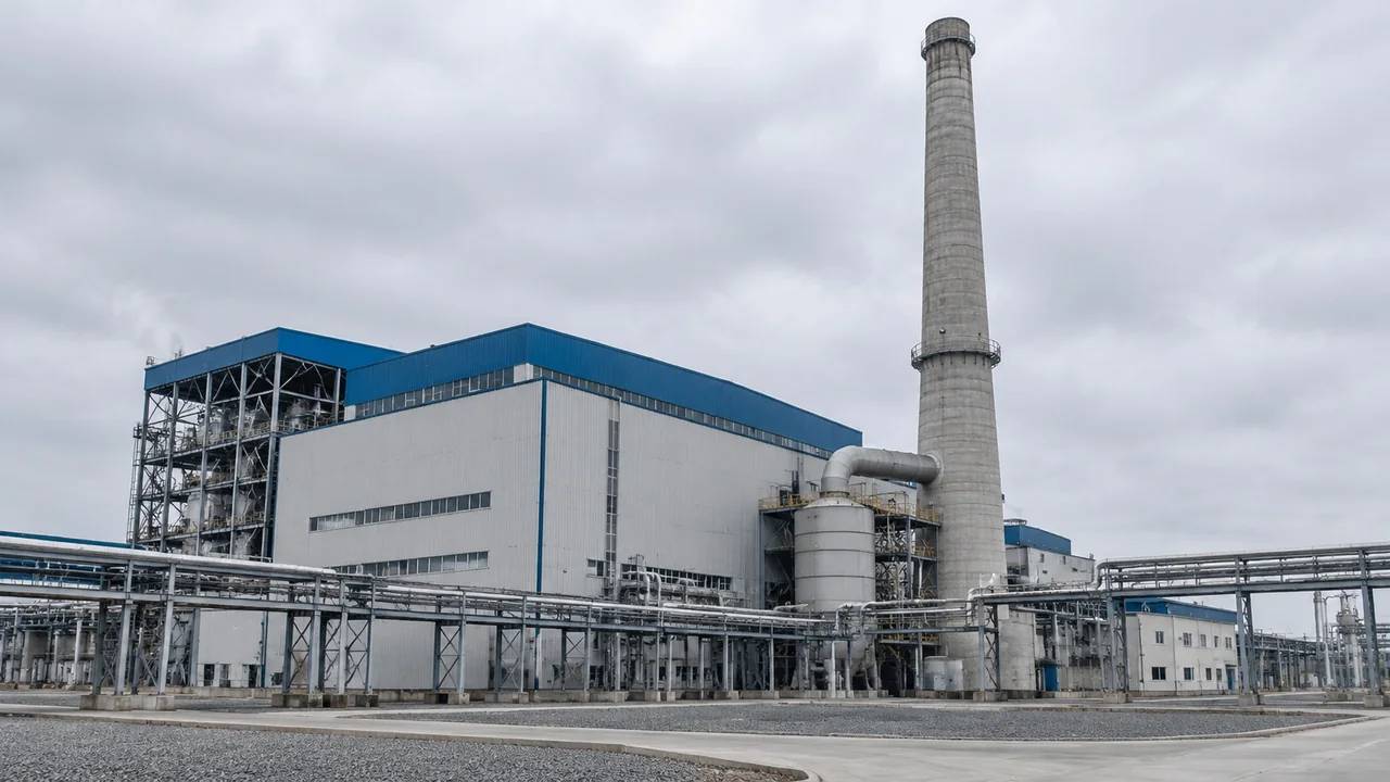
Substation buildings, control rooms and stores have footprints, so they arrive as volumes with estimated heights and inferred types. Switchgear, transformers and inverter stations are equipment and are not generated, which leaves the compound looking emptier than the finished plant. Correct the buildings that carry the layout discussion, then place electrical assets from a library or in the receiving tool. Say which parts of the compound are context and which are still to come. Inverter stations are easy to forget, since they are small, repeated and rarely mapped.
4.2 Buildings that are in the way
An old barn inside the boundary, a farmhouse at the gate, a shed due for demolition: all of them appear until someone edits them. Moving or removing a volume takes a moment and changes how the site reads. Do it before the review rather than explaining the discrepancy live, because a barn standing in the middle of a proposed array field will dominate the opening minutes. On a tight site, one correction often decides whether the layout discussion can proceed at all. Record the change in the note, so it does not reappear later as an unexplained difference.
5 What the layers will not tell you
5.1 Shading, yield and glare
The layers describe ground and cover, not energy. Shading between rows, yield estimates, glare toward a road or an airfield and structural loading on a tracker all need specialist models with their own inputs. A clear scene can make a layout look settled while the number that decides it has not been run. Keep the yield model and the site model side by side, and say which one a slide came from. Bodies such as USGS publish the land cover material behind this kind of study. Keep the two files apart, since a merged one invites the wrong question.
5.2 Soil, drainage and the connection
Ground conditions, flood risk, drainage design and grid capacity sit outside the scene and outside the platform's scope. A layer view can show where a watercourse runs; it cannot say whether a field floods. It can show where a compound sits; it cannot say whether a connection exists or what it would take to build one. Those questions carry their own studies and their own timescales. A layout that ignores them gets redrawn, and the scene will not be the reason.
6 Review order and handover
6.1 A three-step walkthrough
Open with all three layers to show the site as it stands, then terrain alone to discuss rows and grades, then buildings and terrain to place the compound. Each step answers one question and closes it before the next opens. Keep the camera identical between steps so the audience sees the layer change and nothing else. A walkthrough that also moves the camera produces two changes at once, and the room will argue about the wrong one. Name the three steps in the invitation, so people arrive knowing the order.
6.2 Recording the states used
Note the layer state for every image that leaves the review, along with the viewpoint and the imagery date. A drawing over a scene with vegetation hidden looks cleaner than the site will, and that impression travels further than the caption does. Two lines are enough to prevent it. Store the note with the images rather than in a message thread nobody will find in six months. Where several options were compared, keep the same state across the set so the difference on show is the design rather than the display.
6.3 What the export gives a layout team
The GLB carries terrain, water, vegetation, buildings and any edits, ready for 3D, GIS, BIM and engine workflows. It does not carry arrays, trackers, inverters or cable routes, and it holds no yield or shading data. Layout teams use it as ground to design on, and communication teams use it for images of the setting. The platform overview describes the content behind each layer. Test the file in the tool that will open it. Where a layout team already works in one of those tools, ask which format it expects before the export.
Open the GenAnywhere app and frame a solar site
7 FAQ
FAQ-1 Are the arrays a layer?
No. The layers are terrain, vegetation and buildings. Array tables are equipment, designed layout by layout, and they are placed over the scene rather than generated with it. That means they are not switchable with the layer controls and they are not part of the site model. A solar review uses the layers to agree the ground, then places array geometry in the same environment or after export.
FAQ-2 Can I see the ground under a proposed array?
Yes, and it is worth doing before any array is placed. Hide vegetation and buildings to leave terrain alone, then look at slope, fall and any water inside the fence. That view shows where rows would need earthworks and where they would sit on natural ground. It will not tell you how many rows fit, since pitch and table size come from the layout design.
FAQ-3 Do the layers show shading or yield?
No. Shading, yield, glare and tracker loading need specialist models with their own inputs, and none of that is held in the site scene. The layers describe ground surface, cover and buildings. A view can help a group understand where a sensitive neighbour sits, but it cannot say what the plant will produce or how it will look at a given hour of the day.
FAQ-4 Does the export include the panels?
No. The GLB contains the site: terrain, water, vegetation and buildings, plus any edits. Array geometry, trackers and electrical equipment are not generated content, so keep them in a separate file and note the layout version used. The receiving team can merge the two in its own tool if the review still needs the array in place. That also keeps the site reusable when the layout changes, which it usually does.
See how a plant site becomes a shared layout view
Content and technical notes
This article was prepared by the GenAnywhere team with AI-assisted drafting and human review.
Product features, formats, and availability change as the platform evolves; refer to the official GenAnywhere website for current details.
For technical questions or corrections, contact support@genanywhere.com.
Last reviewed: 2026-11-13.