
Wind farm scale: what GenAnywhere covers in one view
A wind farm is a spread rather than a plot, so one scene covers distance well and individual machines hardly at all.
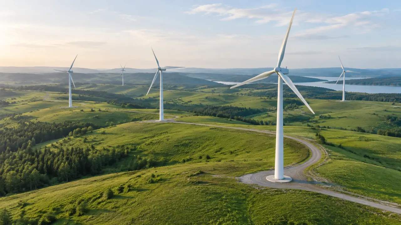
Wind sites run along ridges, across moorland or over several kilometres of farmland, and that shape decides what a single view can show. GenAnywhere generates the ground for the whole spread from map and satellite data: the slopes, the forestry tracks, the clearings and the buildings at the substation. Turbines are design assets, so the view carries the terrain a layout has to work with rather than the machines themselves.
1 What one view can span
1.1 Distance rather than area
Most site models are judged on how much ground they cover; a wind farm is judged on how much distance it spans. A scene can hold a ridge several kilometres long together with the access tracks and the compound at the end, which is the right frame for a conversation about where machines would go. What it will not hold is a close reading of any one position. Accept that trade early, because a wind review that tries to do both in one image usually does neither well, and the audience notices before the presenter does.
1.2 The wider setting
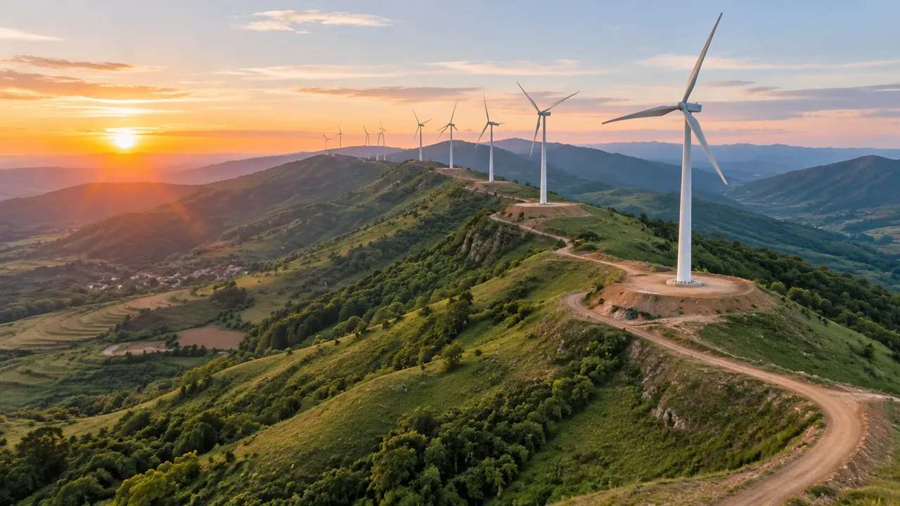
Turbines are visible from far away, so the setting matters more than the site boundary. Include the nearest village, the coast, a neighbouring wind farm or a major road where those features shape the argument. A scene confined to the development area answers a question nobody asked. Generating a second, wider scene for orientation is often more useful than stretching the detailed one, and the two can be shown side by side without any loss of clarity. The audience then knows where the detail sits before it arrives.
2 Ground that decides a layout
2.1 Ridges, slopes and forestry tracks
The terrain follows the mapped ground, so a ridge line, a steep face or a saddle between two summits appears as it is in the data. Forestry tracks wind across slopes in the imagery and show as the routes through the block, which is the constraint a construction planner wants to see. The scene does not assess whether a track can carry an abnormal load, and it does not design a new one. That work needs a transport study and a road engineer, not a wider view. It shows where the existing access runs and where the ground would make a new route expensive, which is usually enough to narrow the options before anyone surveys a route.
2.2 Forest blocks and clearings
Vegetation is generated and managed as its own layer, and on a wind site that layer is a map of what has to be cut. Clearings around existing masts, the edge of the standing crop, the shape of a block that a new track would have to cross: all of it reads at a glance. Hiding the vegetation shows the bare landform underneath and makes the slope pattern clearer. Keep both views in the pack, since one shows the constraint and the other shows the ground.
3 Turbines as assets
3.1 Geometry from a library or vendor
Nacelle, tower and blade geometry comes from a vendor model or a library, not from the platform. That is normal across the industry: machine dimensions belong to the manufacturer, and the site model belongs to the ground. A simplified cylinder at the right hub height is often enough for a layout review and much cheaper than a detailed model. Use the detailed one when the review turns to blade sweep or transport, and say which model was used in any image that leaves the room.
3.2 Placing a mast on the ground the model offers
Once the asset is in the same environment as the scene, the useful questions become visible: does this position sit on the flattest part of the shoulder, how far is it from the track, what stands between it and the ridge. Placing a dozen markers takes minutes and turns an abstract layout into something a landowner can follow. Keep the markers at true height if the audience is discussing visibility, and keep them simple if the discussion is about spacing. Mixing the two intentions in one image is where most confusion starts.
4 Limits
4.1 No wind, energy or shadow work
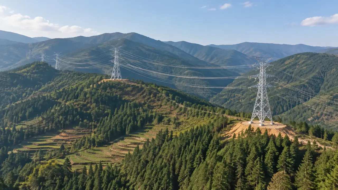
The scene does not model wind resource, wake effects, energy yield or shadow flicker, and it does not assess aviation or radar concerns. Those studies need measurement campaigns, machine data and specialist software, none of which comes from imagery. A scene with turbines on a ridge is a context image for those discussions, not a substitute for any of them. Where a study is needed, bodies such as ISO publish standards that the study will refer to.
4.2 Imagery date and cleared forestry
Forestry changes faster than most land cover, and a block that was felled two years ago may still show as mature crop. Check the imagery date before the review and say it wherever the scene is shown, particularly if access or clearance depended on the felling. A new track cut after the capture will be missing entirely, which matters when the review is about construction access. Ask the site team which areas have changed, and correct what you can.
5 Reviewing a dispersed site
5.1 Two scenes rather than one strained view
For anything longer than a few kilometres, generate a scene for the northern half and another for the southern half, with a shared landmark where they overlap. That gives each view enough resolution to read the ground and enough overlap to keep the audience oriented. Presenting one enormous scene usually ends with a discussion about pixels rather than positions. Two honest scenes also let different teams work on different sections without waiting for each other, which matters on a project with a civil team and an electrical team on the same ridge.
5.2 Distance cues and layer states
Turbines at true height disappear into a wide view, so add a scale cue: a road, a building, a line of trees. Layer states help here, because hiding vegetation exposes the landform and makes slope readable at distance, while showing it restores the sense of scale. Move between the two states rather than stacking them, and caption each image with the state. A wide view with no cue and no caption is the image most likely to be misread later, and the misreading usually travels further than the correction.
Open the GenAnywhere app and frame a wind site
6 Handover
6.1 A list of extents, not one extent
Write down every scene that was generated, with its area and the landmark it was framed around. A wind site usually ends up with three or four, and a handover that names one leaves the rest to be rediscovered. Note which scene each image came from, since two views of similar moorland are hard to tell apart a month later. The platform overview describes what each scene contains.
6.2 What the export carries
Each GLB holds its own extent: terrain, water, vegetation, existing buildings and the edits made before export. It does not hold turbines, cabling or the substation equipment. Teams often export two or three files and assemble them in the receiving tool, which works as long as the overlap is consistent. Test one file before exporting the rest, so a systematic offset is caught early rather than after four exports.
6.3 The receiving workflow
Wind layouts move between GIS, CAD and visualisation tools, and the usual question at handover is which one needs the ground before the others. Say which tool opens the file and what it will be used for: a layout comparison, a landscape image or a base for access design. That answer decides whether the vegetation layer matters and how much of the wider setting should travel. A one-line purpose saves a round of questions, and it keeps the file from being reused for something it was never built to support.
7 FAQ
FAQ-1 How many turbines fit in one view?
The count matters less than the distance. A view can span several kilometres of ridge, which may hold a dozen positions or thirty depending on spacing. Beyond that the ground becomes hard to read and a second scene serves better. Decide the extent from the layout you need to discuss, not from a target number of machines, and split the site when the view starts to lose detail.
FAQ-2 Do turbines appear in the model?
No. Turbine geometry is a design asset supplied by a vendor or an asset library. The platform generates the ground, the vegetation and the existing buildings, and the machines are placed on top of that in the same environment or downstream. A simplified marker at hub height is usually enough for layout work, and it keeps the difference between context and equipment visible.
FAQ-3 Can I show a turbine at its real height?
You can place an asset at the height the manufacturer supplies, and the scene will show it against the ground and the surrounding landform. What the scene will not do is verify the height, the foundation or the transport route. Use it to judge how a machine reads on a ridge from a given viewpoint, and keep the dimensional questions with the machine data and the engineering team.
FAQ-4 Is the scene usable in a consent discussion?
It helps a consent discussion by showing where machines would sit relative to a village, a road or a protected landscape, which is often the point people cannot agree on. It does not produce a landscape assessment, an aviation study or any part of the application itself. Use it to brief the team and to choose which viewpoints deserve a proper study.
See how a wind site reaches a shared scene workflow
Content and technical notes
This article was prepared by the GenAnywhere team with AI-assisted drafting and human review.
Product features, formats, and availability change as the platform evolves; refer to the official GenAnywhere website for current details.
For technical questions or corrections, contact support@genanywhere.com.
Last reviewed: 2026-11-13.