
Water plant expansion: what layout reviews need early, GenAnywhere
Reading grade, ponds, and plant edges before layout work
A water plant expansion runs on constraints that a site plan hides well. Tanks need level ground, basins need room to drain, and new units have to connect to a plant that keeps operating. A 3D view of the site puts those constraints in one place before the layout is fixed.
1 What the ground tells you early
1.1 How does slope affect tank and basin placement?
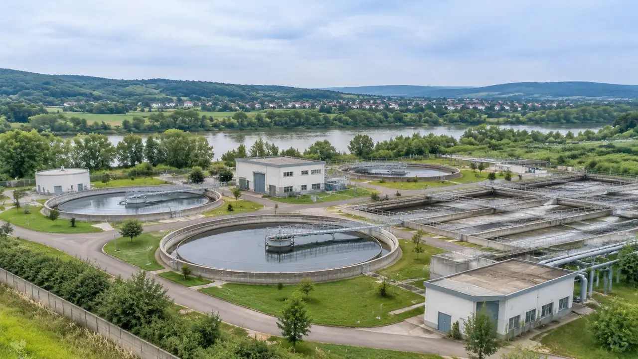
Tanks prefer level ground, and a site with a steady slope forces a choice between benching and retaining walls. A pad cut into the hillside may work for one tank and cost too much for a cluster. Seeing the slope across the whole parcel shows where the flat ground is and how much of it the program would use.
Basins have the opposite problem. They need a low point and a path for water, and a basin placed on a slope may need embankments on several sides. Reading the ground early keeps the basin from landing where the site has to be built up to hold it.
1.2 Where should stormwater and process water go?
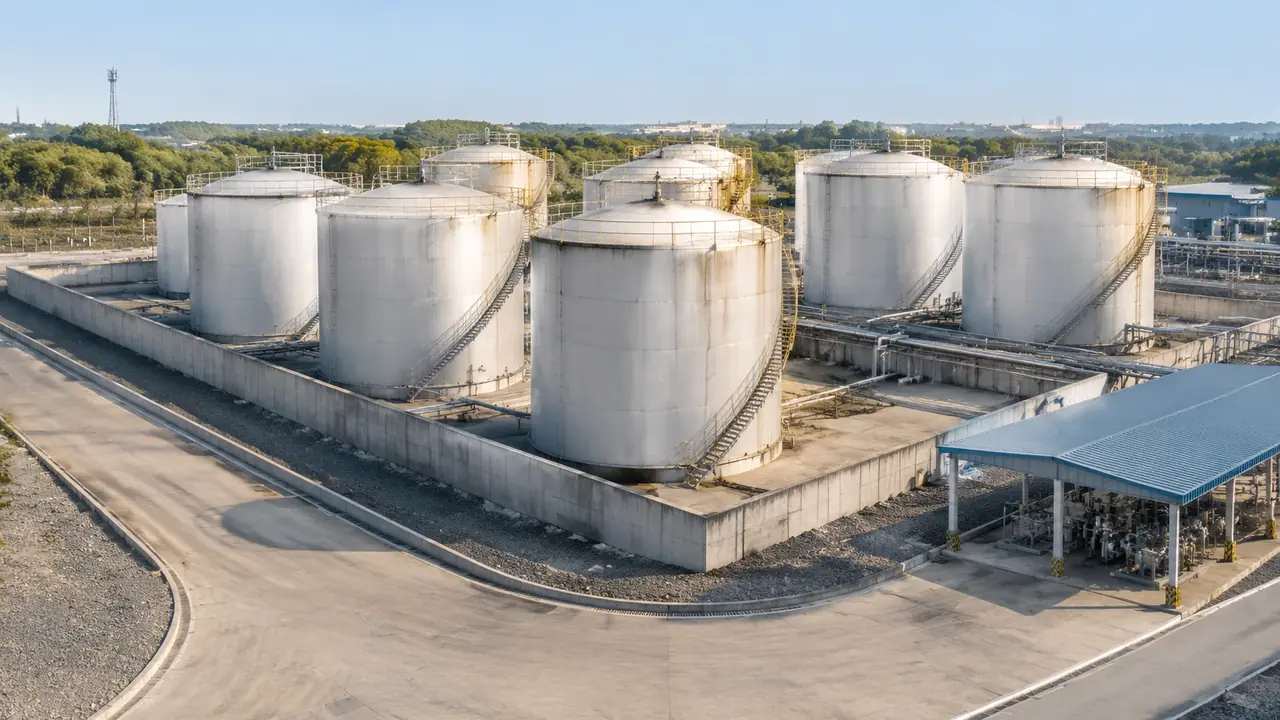
Stormwater and process water follow different rules and often share the same low ground. A plant expansion can change how runoff crosses the site, and a new tank or building can block a path that the drainage plan assumed. The scene shows the surface, so the team can see where water would go if the ground were left alone.
Process water needs a separate conversation with the plant operators. Backwash, residuals, and overflow have their own handling requirements, and the model cannot decide them. What it can do is show whether the space reserved for that handling sits near the units that produce the flow.
2 Fitting new units into an operating plant
2.1 How do tie-ins constrain a layout?
New units have to connect to existing pipes, power, and roads while the plant keeps treating water. A layout that places a new tank on top of a main, or blocks the access to a valve, creates a problem the drawing may not show. Marking the known tie-in points on the site view keeps those conflicts in front of the team.
Clearances matter as much as connections. Maintenance access, crane reach, and the space needed to remove a piece of equipment all shape where a unit can go. A massing model with those zones sketched in is enough to test whether a layout leaves room to operate.
2.2 What space does construction need?
Construction space is temporary, but it can decide the layout. A crane pad, a laydown area, and a route for concrete trucks may occupy ground that the finished plant needs for something else. If the site has no room for that phase, the scheme may need a different sequence.
Phasing adds another layer. An expansion built in two stages may need a temporary connection that later disappears. Showing the site in each stage helps the team see whether the plant can keep running while the work proceeds.
3 Keeping the plant readable in 3D
3.1 What should the scene show?
A useful plant scene shows the buildings, tanks, and ground at a consistent level of detail. It should include the site boundary, the main roads, and the neighbors that affect access or screening. It does not need every pipe, but it should show the corridors where pipes are known to run. Imagery and mapping definitions vary, and bodies such as the American Society for Photogrammetry and Remote Sensing publish terms that teams use when they compare sources.
Too much detail can hurt. A scene that shows every valve invites the group to review valves instead of layout. Keep the model at the scale of the question, and add detail where a decision depends on it.
3.2 How do teams check a view against the plan?
Start with a plan view to confirm footprints and spacing, then move to an oblique view from the gate or the property line. The oblique view shows what a neighbor or an operator would see, which is often different from what the plan suggests. Compare both against the layout drawing before the meeting.
Check heights as well. A tank that looks modest on a plan can dominate a low plant when seen from the street. The scene gives a sense of proportion, though the heights are estimates and should be confirmed for anything that matters.
4 Comparing expansion options
4.1 Which questions should each option answer?
Each option should answer the same short list. Does it fit inside the available ground? Does it keep the plant running during construction? Does it preserve maintenance access? Does it stay clear of the drainage path? Add the questions that matter to the operators, such as whether a unit can be isolated for service.
Score each option against that list and note what remains uncertain. An option that scores well but depends on an unverified assumption should be marked, not promoted. The comparison is there to expose those dependencies.
4.2 What does a scene not settle?
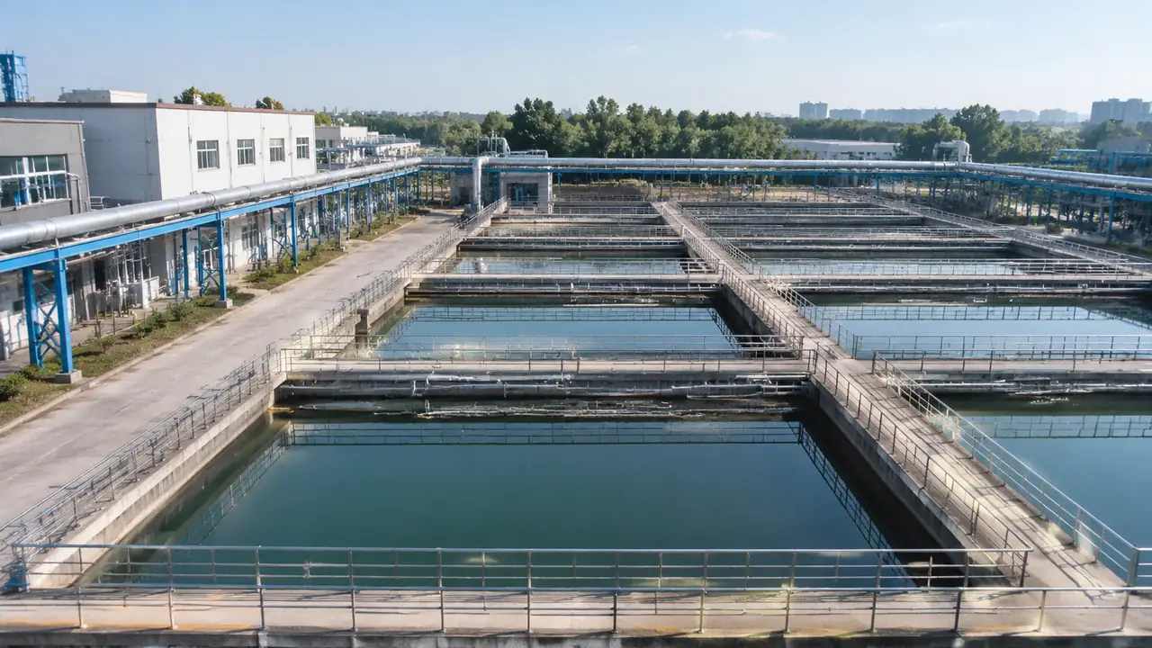
The scene does not settle hydraulics, structural design, or permitting. It cannot tell you whether a pump will deliver the needed flow, whether a tank foundation will work on the soil present, or whether a discharge will meet a permit limit. Those questions belong to engineering and regulation.
It also cannot confirm what is underground. Buried pipes, tanks, and utilities may be missing from any surface view. Utility records and site investigation still decide where digging can happen, and the model should be treated as a planning aid rather than a record of what is buried.
5 Building the review in GenAnywhere
5.1 What can be changed in the model?
GenAnywhere generates a site from a map selection, using map and satellite data for buildings, terrain, water, and vegetation. In a plant review, the existing buildings and tanks arrive as editable objects with estimated heights and inferred types. A planned unit can be represented by replacing a building, moving or rotating it, and adjusting its height or type.
Terrain is generated and matched to the ground, which matters on a site with benches and ponds. Layers separate buildings, terrain, and vegetation, so a review can strip away trees or show the ground alone when the question is about drainage.
A new unit can be represented by replacing a building and adjusting its height or type, which is enough to test how a tank or a building would sit against the existing plant. The edit is quick, so a team can try two positions in the same session and compare them from the gate.
5.2 What does export support?
After preview, the scene exports as a general GLB file for 3D, BIM, GIS, and game engine workflows, including the tools covered in the official tutorials. It is a review asset, not a native plant design model, and coordinate handling depends on the software that receives it.
Test the import before the project depends on it. Materials, units, and origins can shift between applications, and a small trial shows what needs fixing. Open the browser app to build the site, then use the site workflow when the options are ready to compare.
6 Limits and next steps
6.1 When is a visual model the wrong tool?
The model is the wrong tool when the question is about capacity, chemistry, or compliance. It cannot size a tank, confirm a treatment train, or show whether an effluent will meet a limit. Those answers come from process engineering and permitting, and a visual scene adds little to them.
It is also wrong when the site records are incomplete and the team has not checked them. A scene built on outdated imagery can place a tank where a new building already stands. Verify the ground before the review, not after.
6.2 What should the review packet hold?
The packet should include one page per option, the shared question list, the assumptions about unit size and spacing, and a note on source dates. Add the constraints that cannot move, such as a main that must stay in service or a basin that cannot be relocated.
Include photographs from the site visit where they help. A photo of the gate or the maintenance yard can explain a constraint faster than a paragraph. Keep the packet short enough to read in a meeting, and put the open questions at the end.
6.3 How does a team begin?
Choose one expansion scope and build the area it touches. Include the existing units, the proposed footprint, and the access route. Keep the opening pass rough, because the aim is to see whether the site can hold the scope without breaking the plant's operation.
Then review it with operations and maintenance, not just planning. The people who run the plant will spot access problems that a drawing hides. Note their concerns, and use them to refine the next pass rather than defending the initial layout.
7 FAQ
FAQ-1 Can the model size tanks or basins?
No. Sizing depends on flow, storage, treatment process, and regulatory requirements that the scene does not contain. What the model can do is show where a tank or basin of a given footprint would sit and how it relates to the ground, roads, and existing units. Use it to test placement, then take the sizing question to the engineers.
FAQ-2 How current is the imagery?
The scene reflects the map and satellite data available when the site was generated. Construction, tank replacement, or clearing since that date may not appear. Check the capture date and verify recent changes on site before a layout review relies on the scene. If the plant has changed since the imagery was taken, ask for a newer source or walk the area with the operations team.
FAQ-3 Can teams test two expansion options?
Yes. Build both options on the same base scene and review them with the same camera, layers, and question list. Keep the assumptions about unit size and spacing identical unless the option is meant to change them. The comparison shows spatial differences; it does not rank the options on cost or process performance.
FAQ-4 Does the export work with plant design tools?
The export is a general GLB file that many 3D, BIM, and GIS applications can import. Whether a plant design tool accepts it, and what it does with units and origins, depends on that tool. Test the import with a small scene and confirm the path with the team that will use the model.
Content and technical notes
This article was prepared by the GenAnywhere team with AI-assisted drafting and human review.
Product features, formats, and availability change as the platform evolves; refer to the official GenAnywhere website for current details.
For technical questions or corrections, contact support@genanywhere.com.
Last reviewed: 2026-11-11.