
Power grid generation: how GenAnywhere builds a route
The platform generates the terrain and land cover a connection crosses; the line, the towers and the route design arrive from the engineering side.
Grid work starts with a corridor question: what the line would cross, who lives along it, and how the ground rises and falls between two points. GenAnywhere generates an editable 3D site for that corridor from map data, then exports a GLB that a design or GIS team can use as a base. It does not generate the route, the conductors or the towers, and it does not choose where the line goes.
1 What a route scene contains
1.1 The corridor you frame
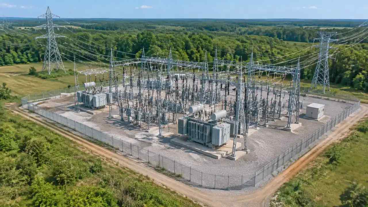
A route scene begins with a rectangle on a map, not with an alignment. You frame the corridor wide enough to hold the land either side of a likely alignment, generate the site, and then treat that strip as the working area for the conversation. Width matters more than length at this stage, because most objections to a line come from what sits a few hundred metres away rather than from the line itself. A corridor that is too narrow removes the neighbours from the discussion. A corridor that is too wide makes the terrain coarse and the file heavy, so the width is worth a minute of thought.
1.2 Terrain, cover and water
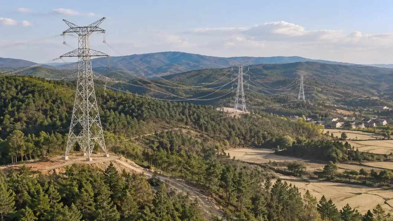
Inside the frame, the platform generates terrain from the mapped surface, water where it appears, vegetation inferred from imagery, and building masses with estimated heights. Ridges, valleys, river crossings and settlements arrive as part of the same scene, which is why a corridor view reads as a place rather than as a strip of white space. Heights are estimates and vegetation is cover, so neither should be treated as a record. The platform overview sets out the generated layers in more detail.
2 Where the route comes from
2.1 Lines are design geometry
A transmission route is designed, not generated. Alignment, tower spotting, span lengths, sag, clearance and structure types all belong to engineering work with its own data and its own checks. In a corridor scene those elements are overlays placed on the generated ground in a GIS, a design tool or a game engine. Saying this at the start keeps the scene in its proper role: it answers what the ground looks like, and the design answers what the line does.
2.2 Tower assets and conductor runs
Towers are equipment. A lattice structure has a type, a height, a foundation and a set of fittings, none of which come from map imagery. Teams bring tower models from a utility library or build a simple tapered block for early reviews, then place them along the designed alignment. Conductors are usually drawn as lines rather than modelled cables, because a catenary at review scale adds weight and little understanding. Label both as assets so nobody reads them as generated content.
3 Generation sites in context
3.1 Plant, substation and switchyard massing
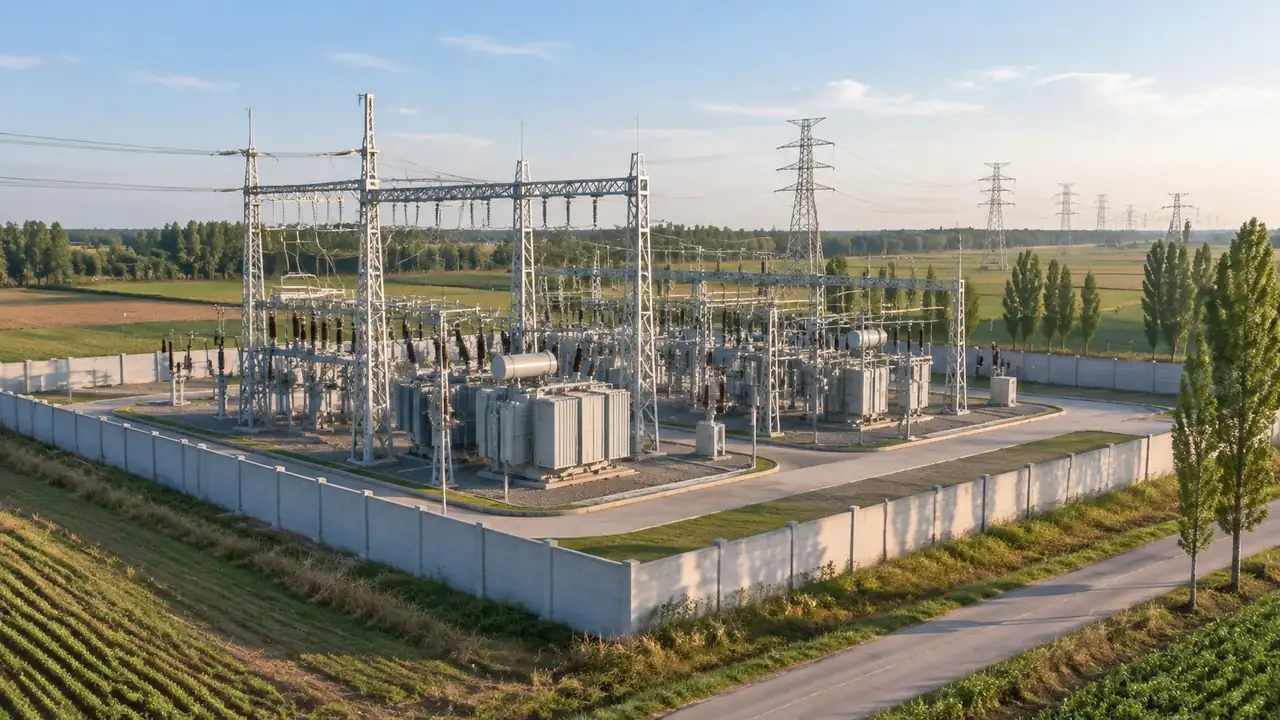
A generation connection usually ends at a site with buildings, a switchyard and a boundary fence. Buildings on that site appear in the generated scene if they have footprints in the map data, with heights estimated and types inferred. A switchyard reads as open ground with small structures, which is recognisable but empty. That emptiness is useful for a siting conversation, since the audience can see the land the equipment would occupy before any equipment is placed. Add the switchyard equipment as an overlay when the conversation turns to layout.
3.2 Terrain and water around a site
Siting arguments often turn on drainage, access and what the site looks like from the road. The generated scene shows the ground slope around a compound, the watercourses nearby and the buildings across the boundary. It will not calculate flood risk or surface water runoff, and it should not be asked to. What it does well is show a site in its landscape, which is the view a planning committee and a neighbouring farmer will both ask for.
4 Limits
4.1 No routing, sag or clearance analysis
The platform does not route a line, calculate sag, check conductor clearance, assess electromagnetic fields or evaluate vegetation encroachment. Those questions need engineering data and specialist analysis, and organisations such as the IEEE publish material that belongs with them. A corridor scene can host the conversation around those studies and cannot replace any of them. Keep the study documents beside the model, not inside it. If a clearance question comes up, answer it from the study and use the scene to show where the span sits.
4.2 Imagery date and vegetation
Vegetation is inferred from imagery, so it reflects the season and year the imagery was captured. A line routed through a plantation that was clear-felled two years ago will look obstructed in the scene, and regrowth since the imagery will be missing. Treat the vegetation layer as an indication of cover, not as a survey of what stands there today. Ask the land team which compartments have changed before the corridor is shown to anyone outside the project. If a compartment is central to the review, mark it with a note rather than trusting the green in the model.
5 Running a corridor review
5.1 A sequence that holds
Open on the corridor in its region, then the crossings, then the segment under discussion. The regional view answers how the corridor sits between towns, rivers and protected land, the crossing view answers what a river or road would require, and the segment view is where tower assets appear. That order keeps the audience from arguing about a single span before they have seen the corridor. If the corridor is very long, split it into named sections and keep one scale.
5.2 Handover
Export the GLB with a note on extent, imagery date and what the file leaves out. A GIS team will want to know whether the terrain arrives as a surface or as objects, and a design team will want to know the origin and units before placing an alignment. Send the tower assets separately and name them, since they carry their own conditions and their own version history. A receiving team that knows what is missing will check instead of assume.
Open the GenAnywhere app and frame a grid corridor
6 Before you export
6.1 Corridor width and length
Decide the width from the decision, not from the drawing. A route selection review needs several kilometres either side to show settlements and crossings, while a tower siting review needs a few hundred metres and more detail. Length can be split across two or three scenes if the corridor runs to a hundred kilometres. Write both dimensions in the note so the receiving team can tell what was inside the frame. Name the end points by place rather than by coordinate, since most reviewers think in places.
6.2 List the missing assets
List the towers, conductors, insulators, substation equipment, access tracks and construction compounds that the scene does not contain. That list is the difference between a context scene and a claim about a built line. It also tells the receiving team what to prepare before the opening workshop, which is usually the difference between a productive session and an hour of file wrangling. Keep it with the export. List the version of each asset as well, since a tower type that changes after the review will invalidate the pictures.
6.3 Say who takes it next
Name the team that receives the scene and the question it is meant to answer. A routing team may want the corridor for alignment options, a stakeholder team may want it for a community meeting, and a GIS team may want it as a base layer for a constraint study. Each purpose implies a different extent and a different note. One export cannot serve all three well, and pretending otherwise wastes the file. Ask the receiving team what question it needs answered, and frame for that question alone.
7 FAQ
FAQ-1 Does GenAnywhere generate transmission lines or routes?
No. The generated set covers terrain, water, vegetation and building masses. A transmission line is design geometry with structures, spans and clearances that come from engineering work. The scene gives that design a place to sit, which is useful for reviews and for early corridor conversations. Describe the line as an overlay whenever the scene is presented, and name the tool that holds the design. A one-line caption under each image does that job without a disclaimer slide.
FAQ-2 Can the platform help route a new line?
It can help the conversation about a route by showing the ground, the crossings and the settlements along a corridor. It does not propose alignments, compare options on cost or check constraints. Routing remains an engineering and stakeholder process. Teams often use corridor scenes to shortlist options visually before any detailed study begins, which is a sensible use of a context model and a poor basis for a decision on its own.
FAQ-3 Are towers and conductors part of the scene?
No. Towers are equipment assets and conductors are design elements, so both arrive from outside the generated site. A utility library, a manufacturer file or a simple block can stand in for a tower during an early review. Conductors are often drawn as lines rather than modelled cables. Keep them grouped as assets so they can be hidden when the conversation is about land rather than structures. A group also makes it simple to swap tower types when the design changes between reviews.
FAQ-4 What about the generation plant itself?
Buildings at a plant or substation appear if the map data carries their footprints, with estimated heights and inferred types. Large industrial structures may read as generic blocks, and equipment inside the fence will not appear at all. That is enough for a siting conversation and not enough for a plant layout review. If the plant is the subject, ask for its drawings and treat the scene as the surrounding context.
See how a generated corridor moves into a GIS workflow
Content and technical notes
This article was prepared by the GenAnywhere team with AI-assisted drafting and human review.
Product features, formats, and availability change as the platform evolves; refer to the official GenAnywhere website for current details.
For technical questions or corrections, contact support@genanywhere.com.
Last reviewed: 2026-11-13.