
Transmission lines: how GenAnywhere builds from a site
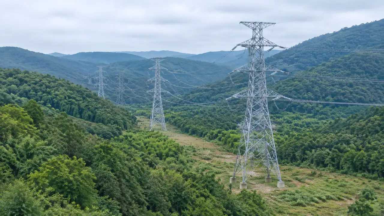
The ground along the corridor is generated; towers, conductors and the route itself are design assets.
GenAnywhere builds a transmission line review from the site outward: you select ground on the map, and the platform generates terrain, water, vegetation and building masses along it. The line is not generated, and neither is the route. Towers and conductors come from the design team, which means the scene answers questions about what a line would cross and how the ground reads beneath it. The pattern repeats whatever the asset: the site comes at the start and the equipment follows.
1 Site before route
1.1 Choosing the end of a corridor
A line review usually begins at a fixed point: a substation, a junction, a crossing that has to be avoided. Start the map selection around that point and let the corridor grow from it, rather than trying to frame the whole route in one selection. Four hundred kilometres of boundary produces a coarse scene that answers nothing well. Two or three selections along the route, each reviewed on its own, will carry a meeting further than one enormous file, and they will load faster on a laptop.
1.2 Extent along a thin corridor
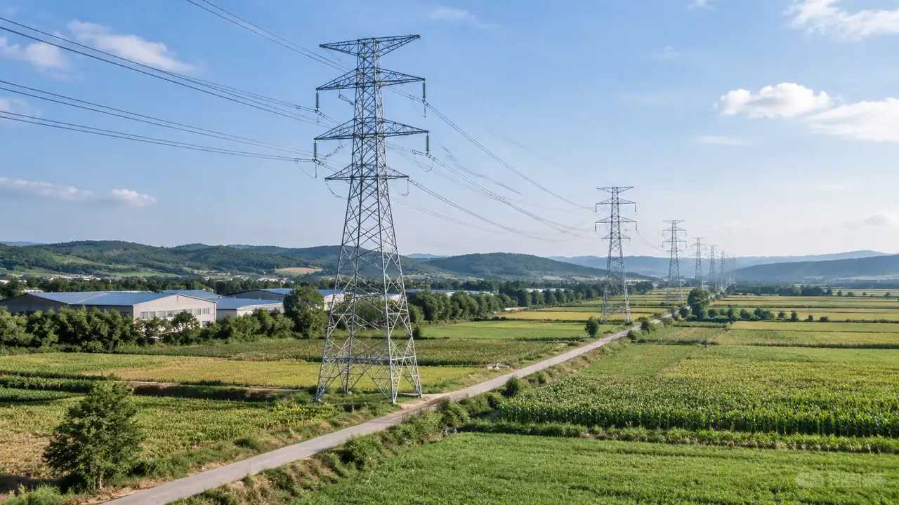
Corridors are awkward shapes: long, narrow, and wider at the points where the line changes direction or meets something else. Draw the boundary a few hundred metres either side of the centreline so the review can see what sits near the line without carrying a whole county. Where the corridor crosses a river or a settlement, widen the boundary locally instead of widening the entire selection. The result is a scene with detail where the decisions are and less where they are not, which is the right trade for a corridor.
2 What the site gives a line review
2.1 Terrain across the corridor
Terrain is the substance of a corridor review, because a line's profile is a conversation between the ground and the structures above it. In the scene you can see where the ground rises into a ridge, where a valley opens, and where a slope would make access difficult for whoever builds the line. Water bodies appear as shapes, so a river crossing is visible before anyone models a tower. None of this replaces survey data, and it is enough to start the argument in the right place.
2.2 Vegetation and buildings near the route
Vegetation arrives as objects with height, which matters more on a line than on most sites: a tree belt near a conductor is a design constraint, not scenery. Buildings are traced with estimated heights, so a farmhouse or a warehouse close to the corridor shows up as a mass with a roofline. Both can be edited when the site has changed since the imagery was captured. Check the ones closest to the route, since those will be raised in the meeting whether you mention them or not.
3 Towers and conductors as assets
3.1 Where the hardware comes from
Tower types, foundations, insulators, conductor bundles and the sag between supports come from the line designer, working in tools built for the job. Standards work on clearances and loading sits alongside that design, and organisations such as the ISO publish material that shapes how those calculations are documented. None of it is generated here. The site model supplies the ground and the obstacles, and the line supplies everything that hangs above them, so neither file has to pretend to be the other.
3.2 Combining for a visual read
In a downstream tool, the tower models are placed along the route and the conductors are strung between them, over the generated ground. That is when a corridor that looked reasonable on a plan shows a ridge in the middle of a span or a tree belt under the lowest point. The read is visual and approximate, which is what an early review needs. Note that the geometry shown is the designer's, and the scene has added just the setting around it, which is the honest way to present a combination.
4 Running a corridor review
4.1 Long extents, narrow views
Keep the camera close to the ground for most of a corridor review, because height flatters a route and hides the things people care about. Use a wide view to show where the corridor sits in the region, then drop to eye level at the three or four places where the line meets something. A long flythrough is impressive and hard to question; a set of fixed viewpoints is easier to argue with, and arguments are what the session is for. Standing still at a viewpoint also gives the quiet people in the room a chance to speak.
4.2 Layers, one at a time
Terrain, buildings and vegetation can be shown as separate layers, which is useful when different reviewers care about different things. A land agent will want the buildings and the vegetation; a structural engineer will want the ground profile and very little else. Turning a layer off is a faster way to answer a question than explaining that the thing on screen does not matter. Agree which layers are on before anyone takes a screenshot, so the picture in the minutes matches the one on screen.
5 Handing the corridor over
5.1 Into a GIS or a design tool
The preview exports as a GLB, which opens in 3D tools, GIS applications and engines, though import behaviour differs between products. In a GIS the scene may arrive as one object or as several layers, depending on settings chosen at import. In a design tool it usually serves as background reference under the line model. Test the import once with the receiving team's own software, then keep a note of the settings that worked, since the next handover starts from those.
5.2 Naming the extent and the version
Name each corridor file by the places at its ends and the date it was generated, because numbers alone stop meaning anything after a fortnight. State which imagery date sits underneath and which buildings you edited. If the route moves, generate a new scene rather than editing the old one into a different shape. Two clearly named files are easier to keep straight than five versions of the same ambiguous one. A file called corridor north with no date invites a guess.
6 Limits on a corridor
6.1 No clearance or sag result
The scene does not calculate conductor clearance, sag, loading or electromagnetic effects, and it cannot be used as evidence for any of them. Those answers come from the line design and from the engineer who signs it. A view can show that a tree sits under a span, which is a prompt to run the check in the right tool, and a reviewer asking for a clearance figure is asking the wrong document. Keep the visual question and the engineering question separate, and both stay useful.
6.2 Imagery date along a long route
A long corridor is likely to cross imagery of different dates, and land cover changes faster than the infrastructure does. Say which parts of the scene rest on older capture, especially where the corridor crosses farmland or recent development. If a housing estate has appeared since the imagery, the scene will not show it, and a reviewer who lives nearby will notice immediately. Asking about recent change is quicker than defending a gap, and a note about coverage is easier to accept than a discovery.
6.3 Export terms and missing assets
The GLB carries the generated site and your edits, and it does not carry towers, conductors or foundations. The licence is permanent and commercial, with limits on reselling raw files and on using them to train models. Tell the receiving team which assets are missing and where they will come from, so nobody opens the file expecting a line. A short list of what is absent is more useful than a long description of what is present, and four lines are usually enough.
Open the GenAnywhere app and select a corridor site
7 FAQ
FAQ-1 Does GenAnywhere generate transmission towers?
No. Towers, foundations, insulators and conductors are design assets from the line engineer, and the platform generates the ground the line crosses: terrain, water, vegetation and building masses. Teams combine the two in a downstream tool. Expect the scene to explain the corridor and the line model to explain the structure, with a check of scale once they meet.
FAQ-2 How wide should the corridor selection be?
Wide enough to include whatever the review will point at, usually a few hundred metres either side of the centreline. Widen it locally at rivers, settlements and changes of direction rather than along the whole route. A narrow strip saves nothing and hides the neighbours, while a very wide one thins the detail where the line actually goes. A corridor that hides the neighbours hides the objections too.
FAQ-3 Can the scene show conductor clearance?
No. Clearance is a design calculation, not a property of the site model. The scene can show a tree belt or a building near a span, which is the visual prompt that sends someone to run the calculation in the design tool. Use the picture to decide where to look, and use the design model to answer what you find there. The distinction is simple once it is said out loud.
FAQ-4 What does the export contain?
Terrain, water bodies, vegetation and building masses along the selected corridor, plus any edits you made before previewing. It does not contain towers, conductors or route geometry. Confirm the scale and origin in the receiving application, note the imagery date, and keep the scene file so that a re-export is a short job. State that date in the same note, because the two questions always arrive together.
See how a corridor site moves into a line design workflow
Content and technical notes
This article was prepared by the GenAnywhere team with AI-assisted drafting and human review.
Product features, formats, and availability change as the platform evolves; refer to the official GenAnywhere website for current details.
For technical questions or corrections, contact support@genanywhere.com.
Last reviewed: 2026-11-13.