
Solar generation: how GenAnywhere builds a plant site
The site is ground, water, planting and a few farm buildings; the array is a design object laid over it.
GenAnywhere builds a solar plant site by taking an area from the map and turning the imagery inside it into editable terrain, water, vegetation and building masses. That is the setting for a generation project, not the project itself. Modules, mounting structures, inverters and cabling come from the design team, so the scene answers questions about where a plant could sit and what it would sit among. Teams expecting a finished array will be disappointed by that, and teams that need the ground will not be.
1 Starting with a plot and a map
1.1 Choosing a plot worth a look
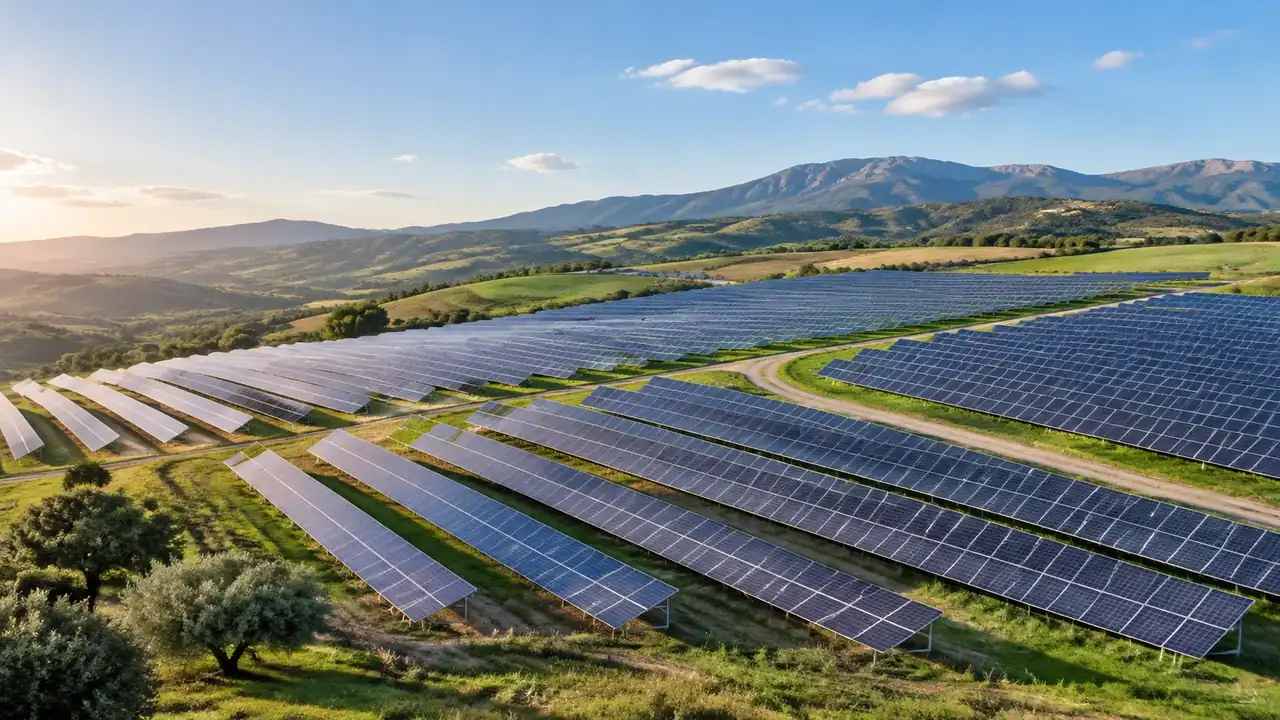
A generation project usually starts as a shortlist of plots, and each one needs a look before anyone spends money on it. On the map, the plot is a boundary drawn around fields, and the platform builds the site inside that boundary within a working session. Draw the boundary a little wider than the land you are considering, since the review will mention the road, the houses and the treeline at the edge. A tight boundary produces a scene with no neighbours in it, and a boundary drawn in a hurry is the usual reason a scene needs redoing.
1.2 Reading the record before the design
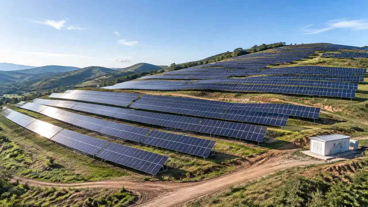
Imagery shows the plot as it was on the day of capture, which for farmland can be a season out of date. A field that was ploughed may now be in grass, and a barn shown on the image may have come down last winter. Check the capture date before you treat the scene as a description of the site. Local knowledge fills the rest, and a short call with the landowner usually settles more than another hour of drawing boundaries at a desk.
2 What the plant site is made of
2.1 Terrain and water
Terrain is generated as an editable surface, and on a candidate plot it is the most useful thing in the scene. You can see where the ground rises, where a hollow would hold water and how a low ridge would screen the site from a house. Water bodies appear where the imagery shows them, including ponds and wider ditches that read as water at that resolution, and they arrive as shapes rather than as hydrology. None of this replaces a ground survey, and the platform overview describes what the generated set contains.
2.2 Vegetation and field edges
Vegetation arrives as vegetation, so a hedgerow is a row of objects rather than a green line on the ground. That matters on a generation site, where the hedge is often the thing a neighbour cares about most and the thing a layout has to work around. Field edges, tree belts and scrub all come through at the resolution of the imagery, which is coarse enough to miss a young orchard. Walk the edge of the site in the scene, then check anything that looks thin against a photograph taken on the ground.
3 Buildings on a generation site
3.1 What the platform finds there
Buildings on farmland are small and few: a barn, a shed, a farmhouse, maybe a small industrial unit on the next plot. The platform traces footprints, estimates height and infers a type, which is enough to show scale against a proposed compound. It will not tell you what is inside, whether the roof is sound or how much load it carries. Those questions belong to a building survey, and if the review needs them, send someone to look. A shed that turns out to be listed changes the options more than any choice of module.
3.2 Editing masses for options
Building masses can be moved, rotated, resized and retyped, which makes them useful for testing a question rather than describing a fact. If the design needs a substation compound where a barn stands, delete the barn and see what the site looks like with a plain building of that size in its place. The edit is a sketch, and it should be labelled as one. Keep the unedited version of the scene, because the site as found is the reference every option is measured against.
4 Panels are a design object
4.1 Where the array comes from
Module rows, table spacing, tracker geometry and inverter stations are design decisions, and the platform does not produce them. They come from the engineering team, usually as a layout in a CAD or PV design tool that has already considered tilt, pitch and the local wind load. Standards work behind those assumptions, such as the material published by the IEEE, sits with the designer rather than with the site model. The site's job is to show the gradient, the hedge and the neighbour's roofline that the array has to answer.
4.2 Combining site and array
The two are brought together downstream, in a 3D tool, a GIS or a game engine, where the array is placed on the generated ground and viewed from the boundary. That is when a layout that looked tidy on a plan shows that it runs into a hedge or climbs a slope. The check is visual and quick, which is the point of doing it early. Anyone who has reviewed a layout flat on a screen knows how much a slope changes the reading, and how late that usually happens.
5 Reviewing with the ground held fixed
5.1 A sequence for a siting meeting
Start wide enough to show the plot in its landscape, then move to the boundary and the nearest houses, then to the compound area. Each step answers a different objection, and taking them in order stops the meeting from opening with a debate about panel height. Keep one viewpoint for the whole session so that later images can be compared with the early ones. Agree each constraint in words before moving on, and the session closes with a list rather than a feeling.
5.2 Comparing two plots
When the shortlist has more than one plot, generate both sites and keep the same camera positions where the terrain allows. Reviewers can then compare how each plot sits against its neighbours without arguing about drawing style. Two scenes are more work than one, and still less work than rebuilding a site in the design tool for each option. Name the plots the way the landowner names the fields, since that is the name everyone in the room will recognise.
6 Limits at the plant boundary
6.1 No yield or shading figure
Nothing in the scene calculates generation, shading loss, soiling or return, and it should not be asked to. Those numbers come from an energy model fed with measured irradiance, module data and an agreed layout. A view can show that a treeline sits close to a proposed row, which is a useful prompt for the energy model, but it cannot say what the loss would be. Keep the two conversations apart and each one stays credible.
6.2 Change on a working farm
Farmland changes faster than most industrial sites: hedges are cut, barns go up, drainage is improved. The imagery date is the boundary of what the scene knows, and edits cover just what you noticed. Ask the landowner what has changed since the date on the image, and correct the buildings that moved. A site model with three known corrections is more useful than one presented as untouched imagery, and those corrections give the meeting something concrete to agree on.
6.3 Export and licence
A previewed scene can be exported as a GLB for 3D, BIM, GIS and engine workflows, carrying terrain, water, vegetation, buildings and your edits. Panels and plant equipment are not in the file, so tell the receiving team what they will need to add. The licence is permanent and commercial, with limits on reselling raw files and on training models with them. Read those terms once before a client asks, and export again after further edits rather than patching the file.
Open the GenAnywhere app and frame a generation plot
7 FAQ
FAQ-1 Does GenAnywhere design the solar array?
No. It builds the site around the array: terrain, water, vegetation and buildings. Module rows, spacing and the electrical layout come from the design team and their own tools. The scene gives that design a real setting to be tested against, which is where most siting disagreements actually live. Expect to combine two files, not to receive one finished proposal.
FAQ-2 Which site features matter most in the scene?
The ground shape, the water, the vegetation at the boundary and the nearest buildings. Ground shape decides where a compound can sit, water decides where it cannot, and the boundary vegetation is usually the neighbour's main concern. Buildings give scale to a proposal that would otherwise be a rectangle on a field. Look at those four before the conversation turns to modules.
FAQ-3 Can I compare two candidate plots?
Yes, by generating each site and reviewing them with similar viewpoints. Keep the same camera height and angle where the terrain allows, or the comparison turns into an argument about perspective. Export both scenes if the design team needs to test a layout on each. Two site files cost far less than choosing a plot from a plan alone and finding the problem later.
FAQ-4 What does the exported file contain?
The generated site and your edits: terrain, water bodies, vegetation and building masses. It does not contain panels, inverters, cabling or engineering data, and it carries no energy model. Confirm the scale and origin in the receiving tool before the meeting, and note which version of the site the layout was reviewed against. Keep the scene until the receiving team confirms that the file opened as expected.
See how a generation site moves into a design workflow
Content and technical notes
This article was prepared by the GenAnywhere team with AI-assisted drafting and human review.
Product features, formats, and availability change as the platform evolves; refer to the official GenAnywhere website for current details.
For technical questions or corrections, contact support@genanywhere.com.
Last reviewed: 2026-11-13.