How to Import Vector Data and Generate Building Models in GenAnywhere
GenAnywhere is a tool that requires no aerial photography — just select an area on the map to AI-generate 3D building scenes, streamlining BIM modeling and providing an efficient, cost-effective alternative to oblique photogrammetry.
In the top toolbar of the GenAnywhere workspace, a new "Import Vector Data" feature has been added. This feature can import "Building Outlines" and "Region Outlines," and directly generates 3D building models based on the outlines we import.
This article describes the specific operation flow for importing vector data and generating building models in one click in GenAnywhere.
1. Import Vector Data
1.1 Introduction to the Import Vector Data Feature
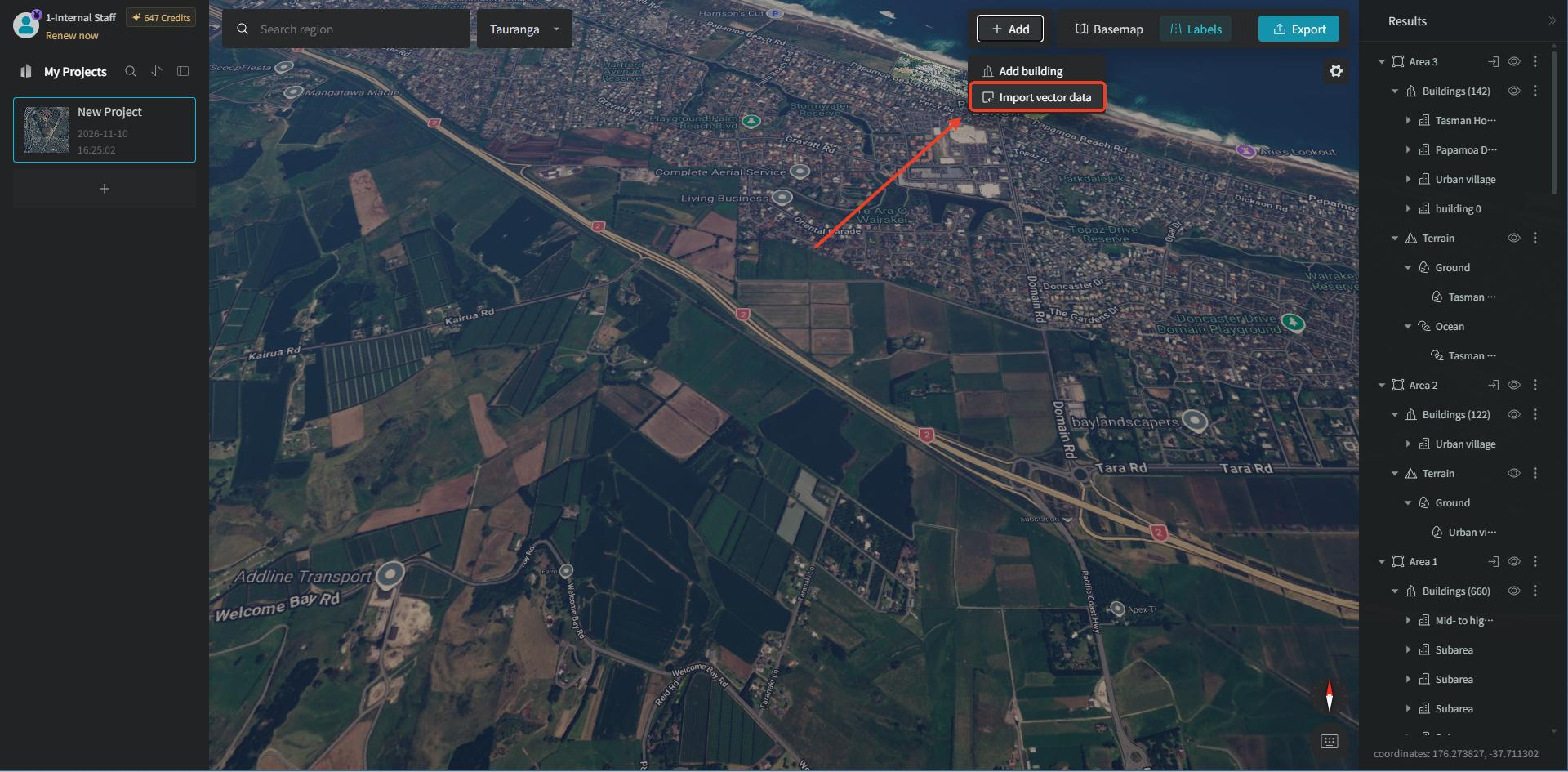
After we create a new project in GenAnywhere, click the "Add" button on the right side of the top toolbar. In the popup function options panel, there are two items: "Add Building" and "Import Vector Data." The "Add Building" feature is only supported in single-building preview mode. "Import Vector Data" is mainly used to bring in external vector data and, based on the uploaded vector data together with the AI recognition generation capability, generate 3D models.
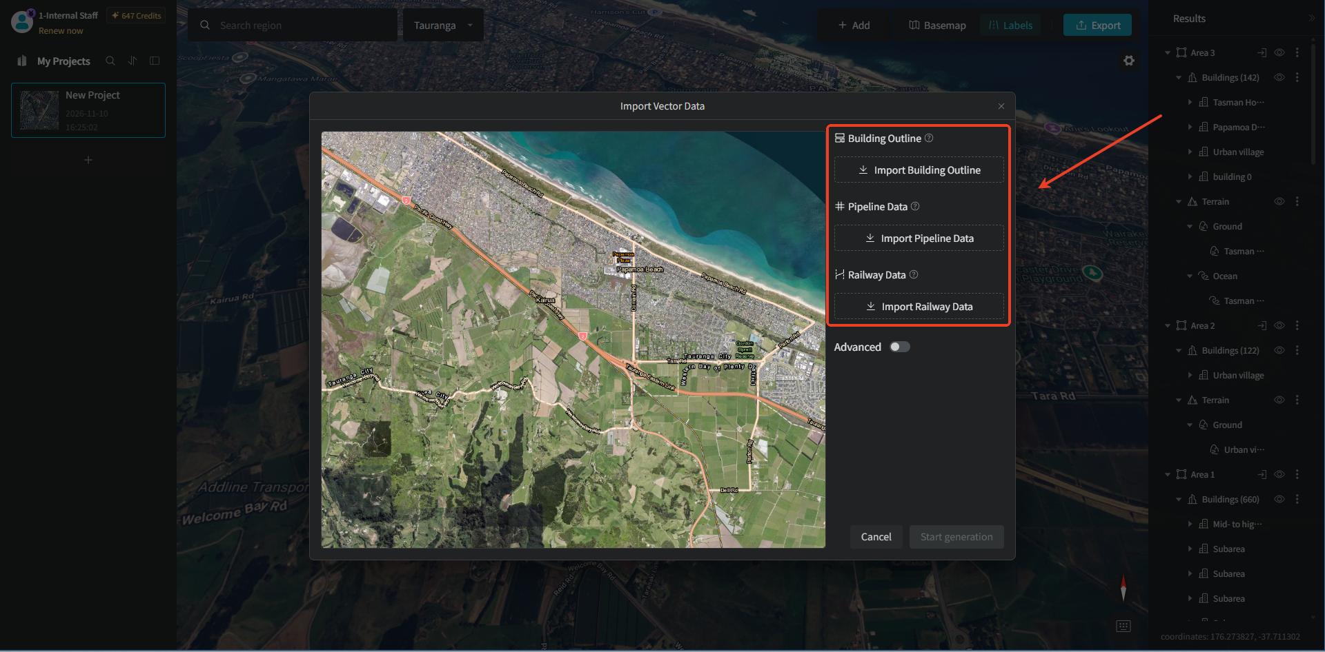
After clicking it, the "Import Vector Data" dialog pops up, with the basemap viewport on the left and a configuration panel on the right; the "Advanced" switch is currently off.
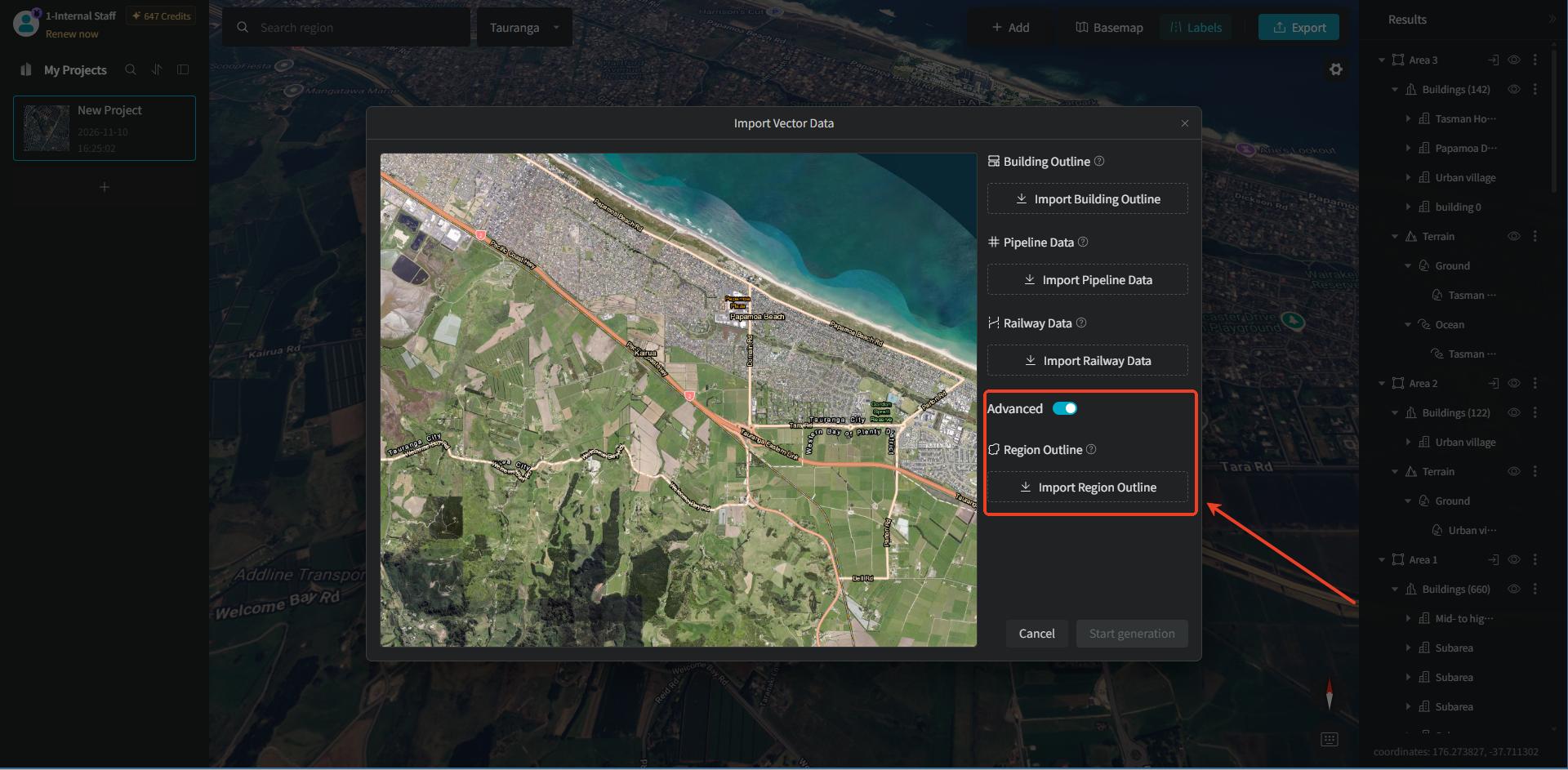
When the advanced option is turned on, the "Region Outline" vector import item is displayed.
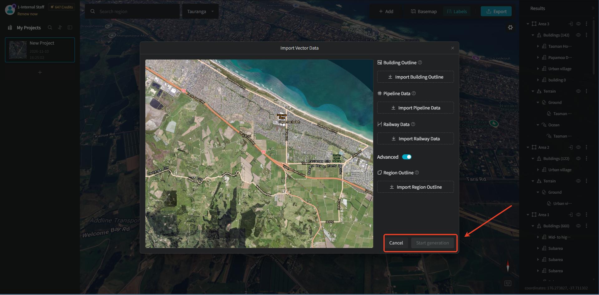
At the bottom of the dialog, "Cancel" and "Start Generation" action buttons are provided, to complete the vector data import and batch-build 3D building blocks.
2. Building Outline
2.1 Import Building Outline Vector Data
"Building Outline" uses the building outline as the generation range, preserving the original building position and outline shape. In the "Import Vector Data" dialog, click the "Import Building Outline" button under "Building Outline" on the right. Then, in the "Import Building Outline" window, file drag-and-drop / click-to-upload is provided, supporting "GeoJSON" or a ZIP containing a complete set of "SHP" data.
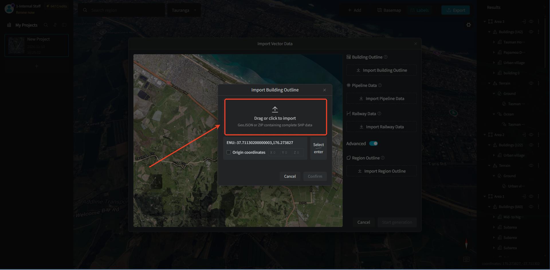
Generally, the system automatically obtains the "coordinate system." If retrieval fails, you can click "Select/Enter" to choose it manually.
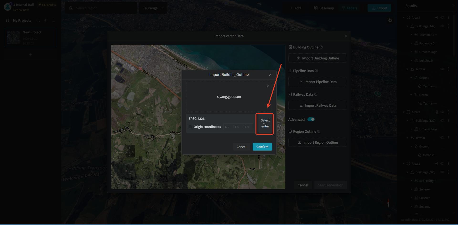
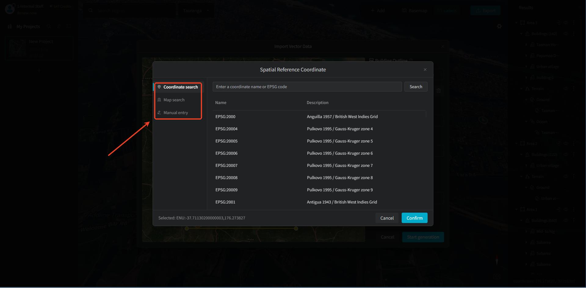
You can set the "spatial reference coordinates" through "coordinate search," "map search," or "manual entry" — choose as needed.
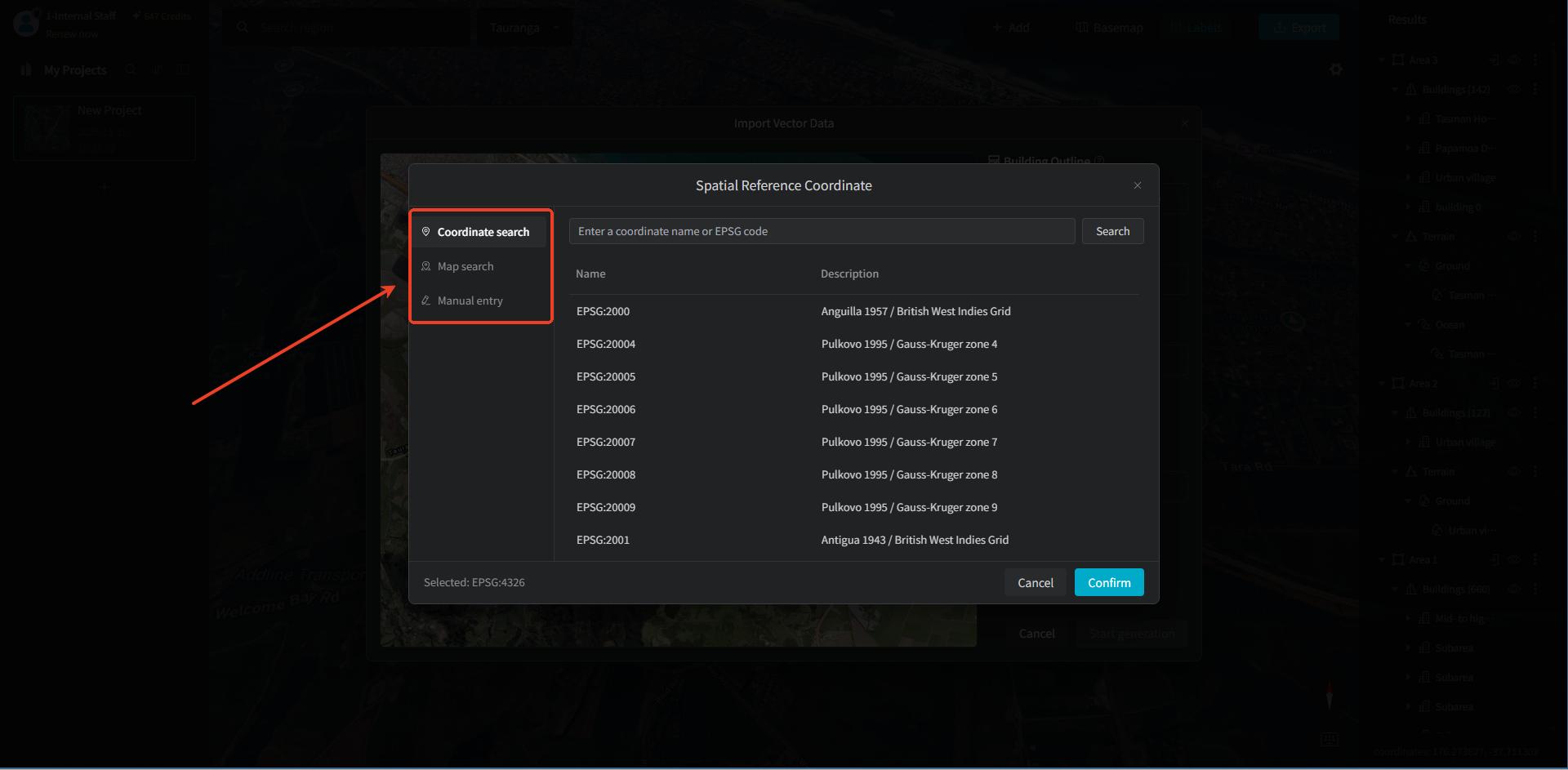
When done, click the "Confirm" button. The satellite imagery viewport on the left has loaded the imported building outline vectors; the orange polygon features are building outlines, and the yellow outer frame is the data range boundary.
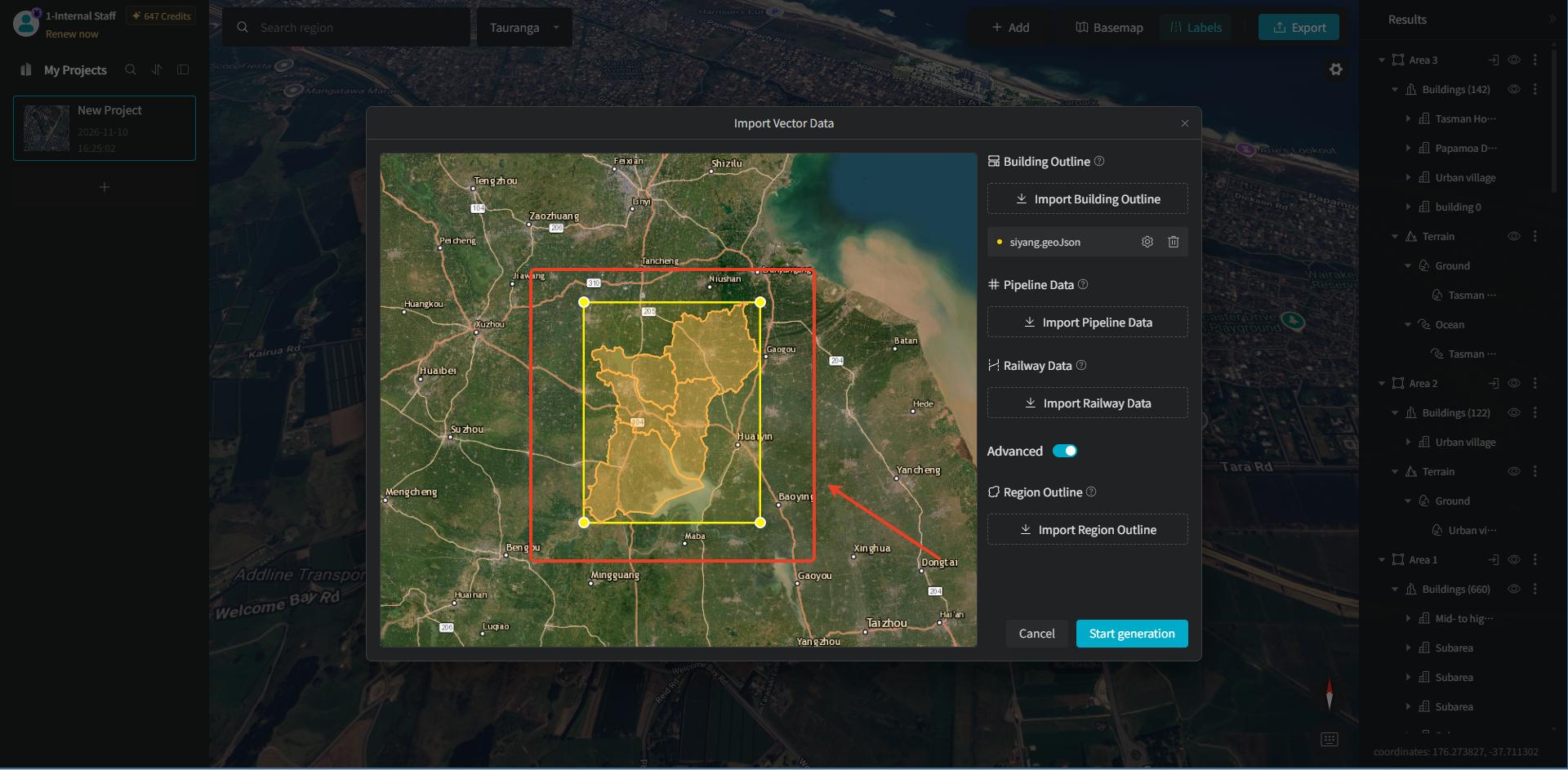
We can drag the endpoints or center points of the yellow outer frame to expand the selection range. In addition to the buildings that are fixed-generated from the vector data we imported, the expanded range will also generate building models.
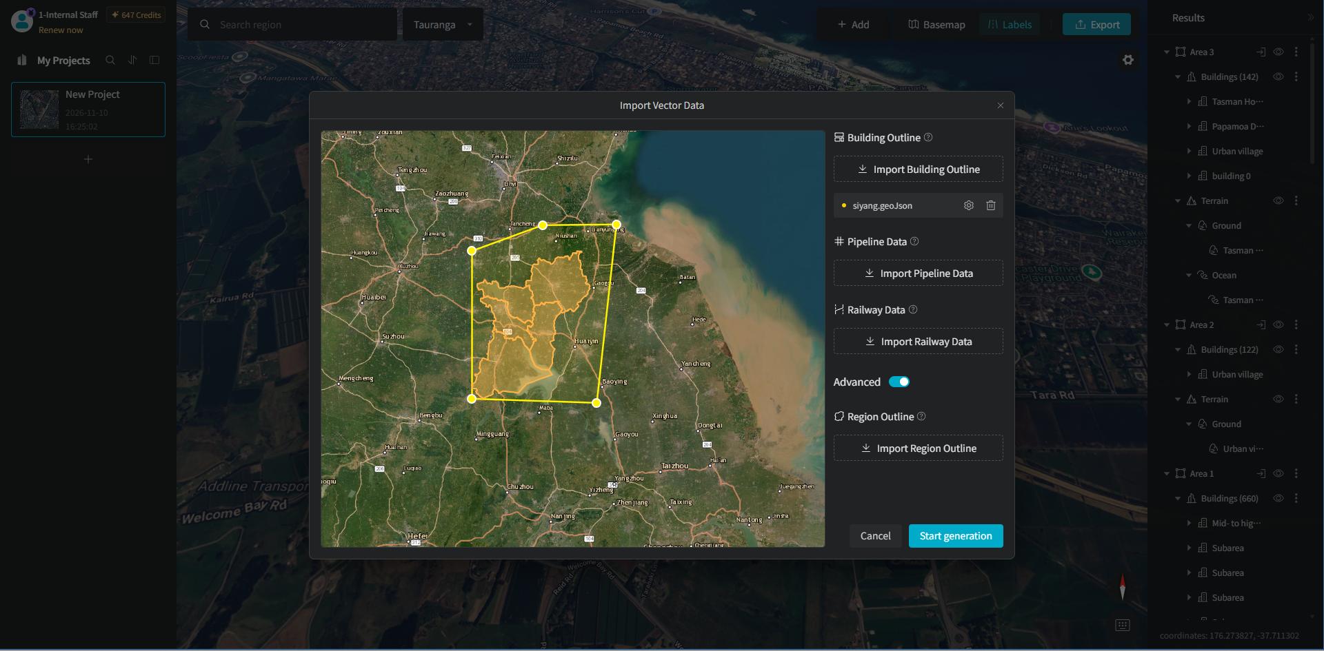
2.2 Set Height Attributes
Click the "Settings" button to the right of the loaded vector item; a "Height Attribute Name" configuration item is provided, supporting switching between "Height" and "Level".
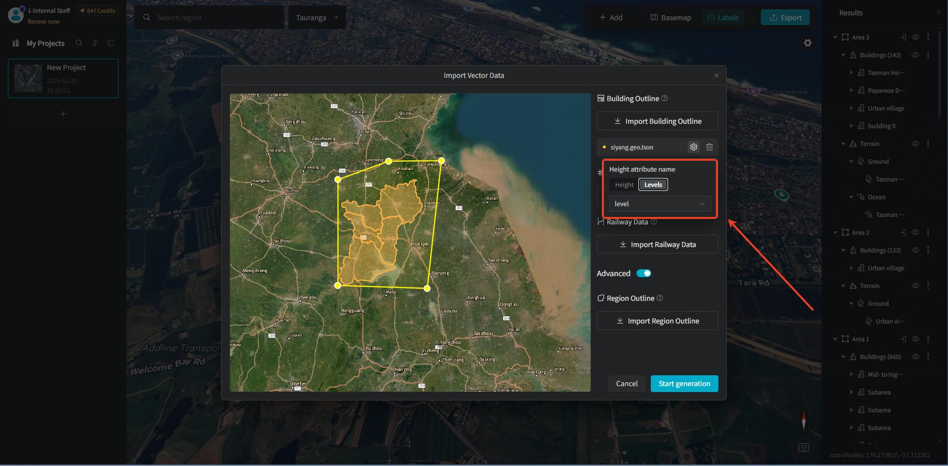
If the software recognizes attributes in the vector data, click the dropdown to select a vector attribute field, mapping the vector attribute to the building elevation parameter and automatically driving the height assignment of 3D building blocks.
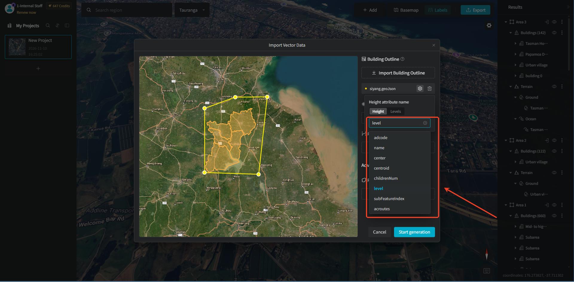
If no attribute field is recognized, the dropdown will display "Not selected, use AI recognition" by default, and the buildings will be generated based on AI recognition afterward.
3. Region Outline
3.1 Import Area Outline Vector Data
"Region Outline" means using the area outline as the generation range, automatically recognizing and generating the scene model within the range. Turning on the "Advanced" option displays "Region Outline."
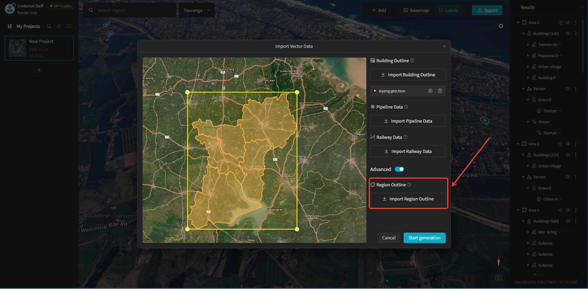
Click the "Import Region Outline" button under "Region Outline" on the right. Then, file drag-and-drop / click-to-upload is provided, supporting "GeoJSON" or a ZIP containing a complete set of "SHP" data.
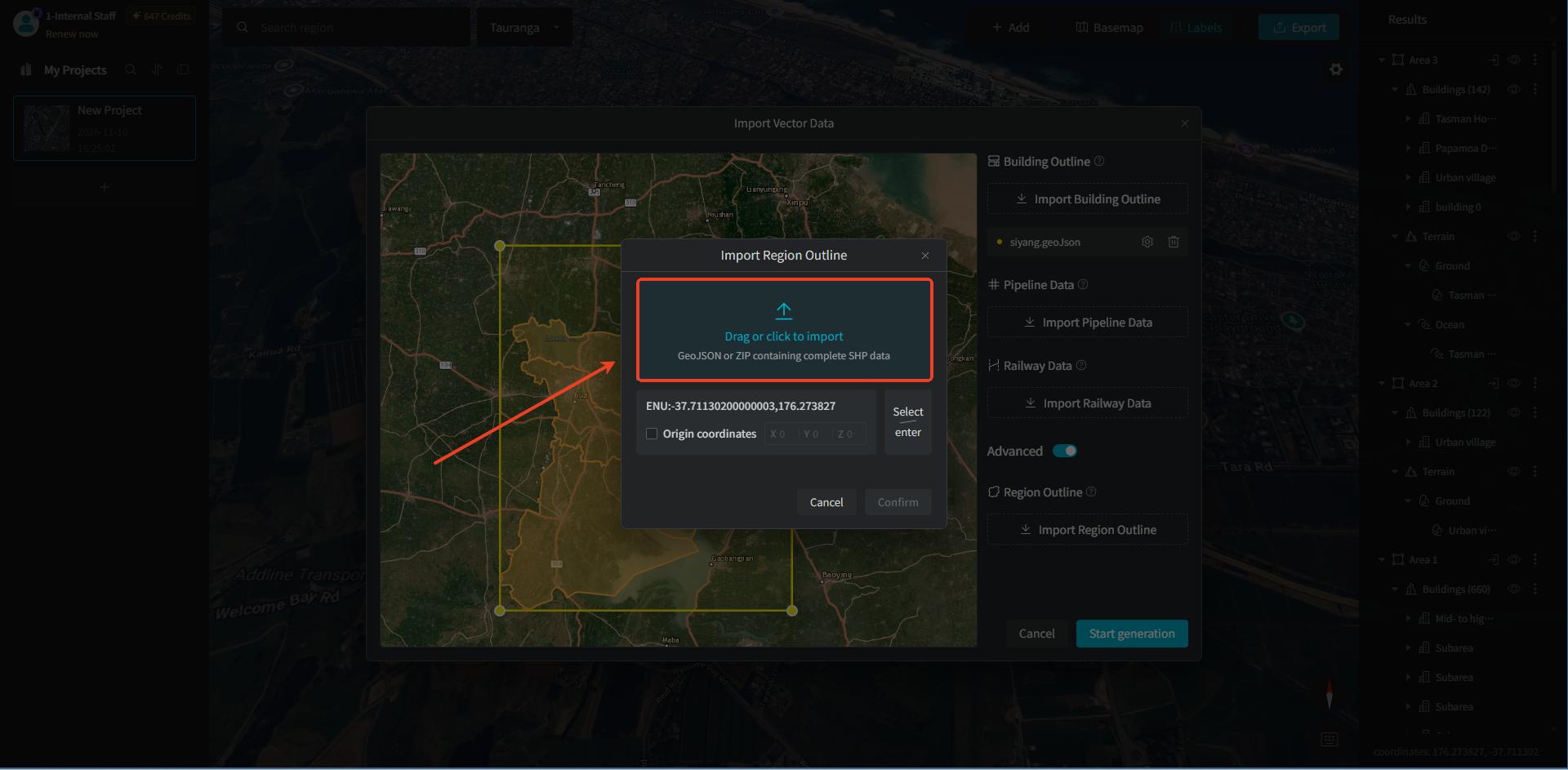
Generally, the system automatically obtains the "coordinate system." If retrieval fails, you can click "Select/Enter" to choose it manually.
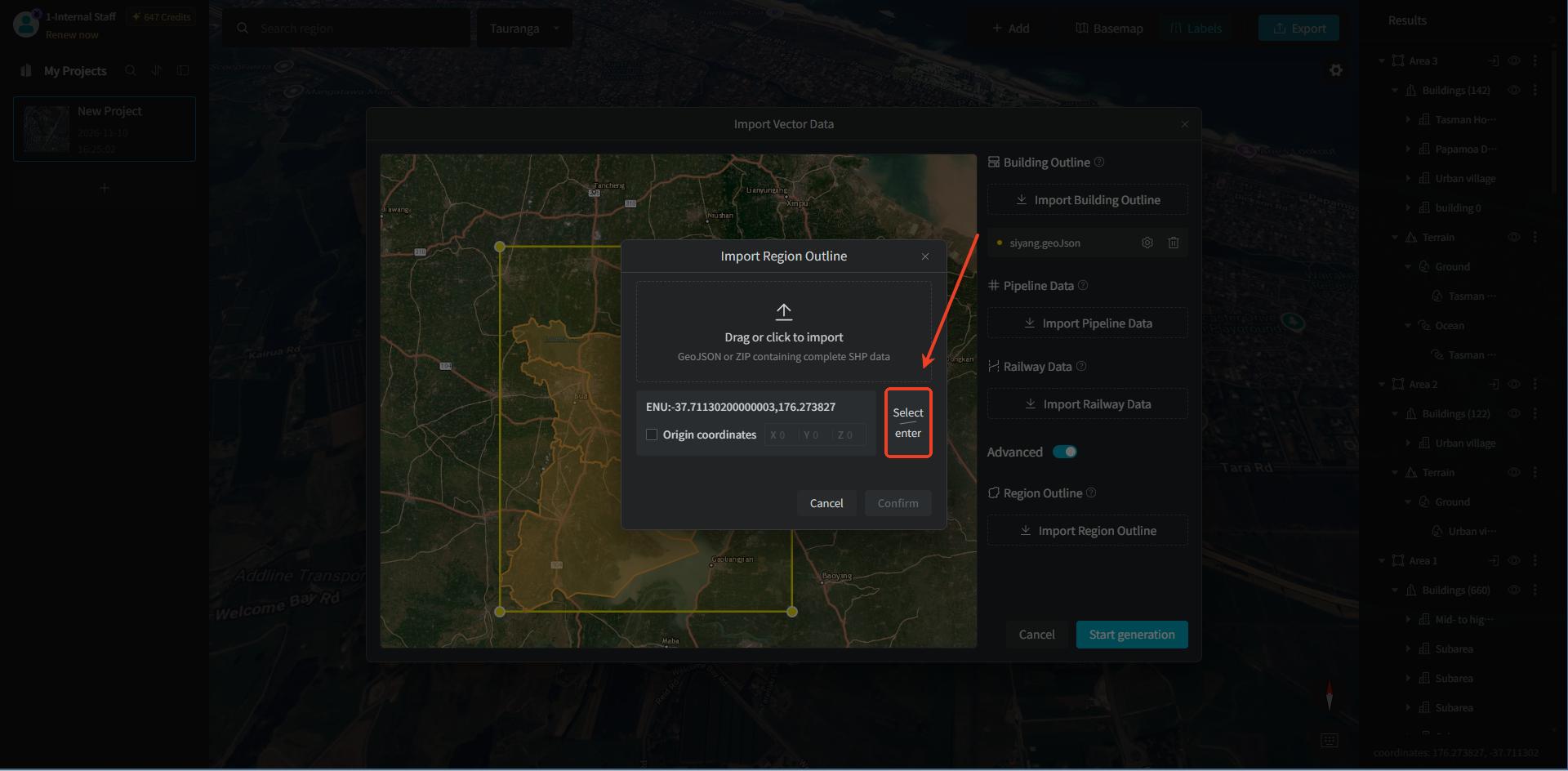
You can set the "spatial reference coordinates" through "coordinate search," "map search," or "manual entry" — choose as needed.
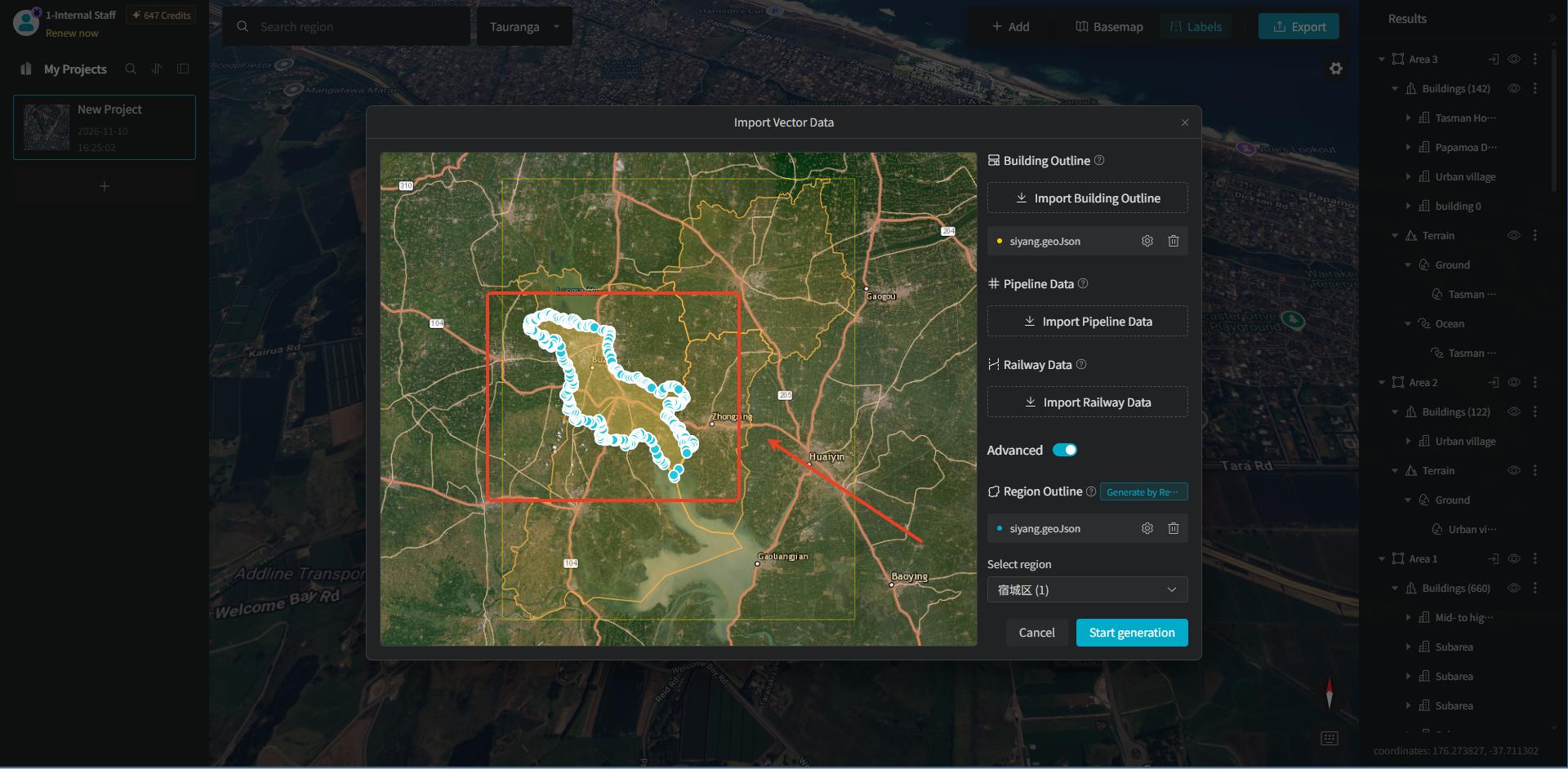
After importing the area vector data, click the "Confirm" button, and we can see that the area framed in blue is the vector data of the area outline we imported.
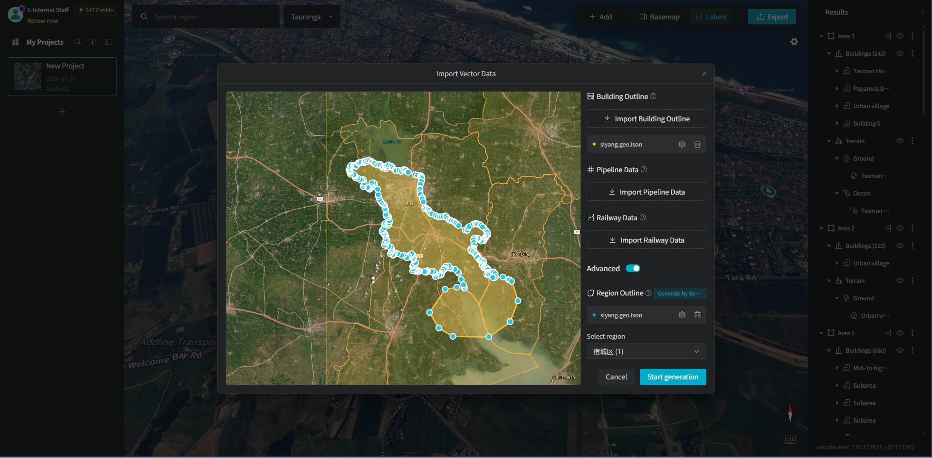
Likewise, we can drag the endpoints or center points of the blue outer frame to expand the selection range.
3.2 Settings
3.2.1 Generate by Area Outline
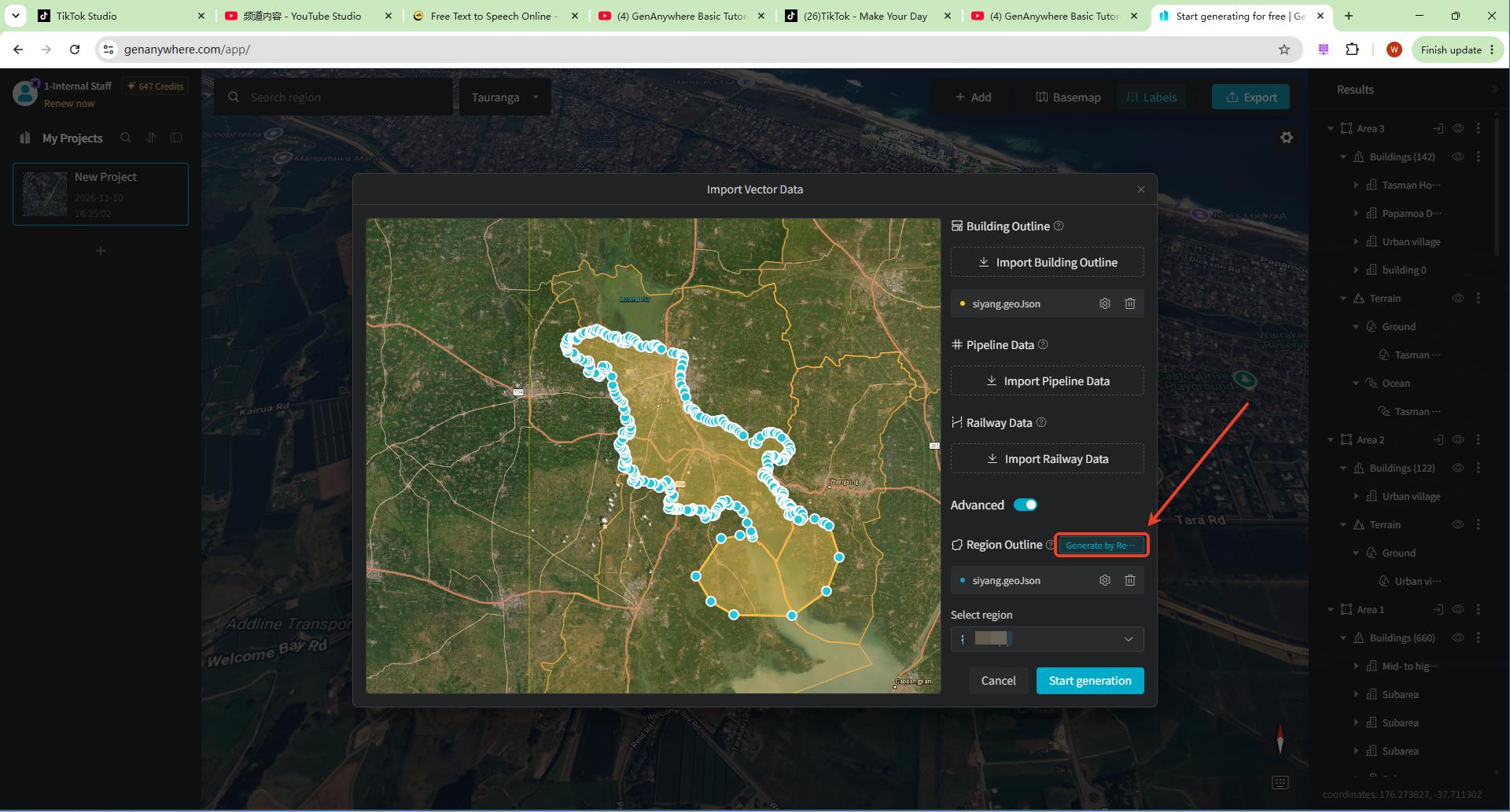
When we import area outline vector data, we will notice that the right panel displays "Generate by Region Outline," and at this point the yellow outer frame of the "Building Outline" we imported earlier becomes noticeably fainter. So the building models we generate will also only be those within the blue frame.
3.2.2 Automatically Expand the Range
If we want the uploaded "Building Outline" and "Region Outline" to generate building models at the same time, click the "Settings" button to the right of the loaded vector item, and a "Generate by Region Outline" toggle control will be displayed. When the toggle is on, the generation range is limited to the current area outline; when it is off, the outer bounding range is generated based on all uploaded outlines.
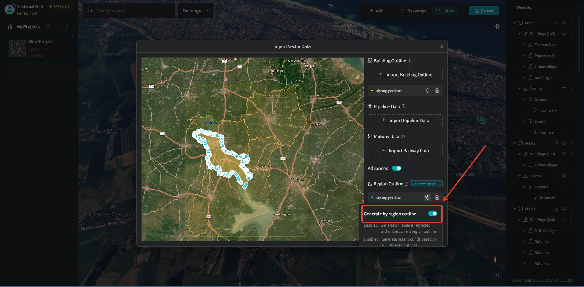
After turning it off, the left panel also displays "Automatically Expand Range." In the satellite imagery basemap viewport, multiple sets of polygon vector features are overlaid: the yellow border is the building outline vector range frame, and the orange polygon features inside are the building footprint outlines; the blue border is the area outline polygon feature; the purple outer frame is the overall outer bounding boundary.
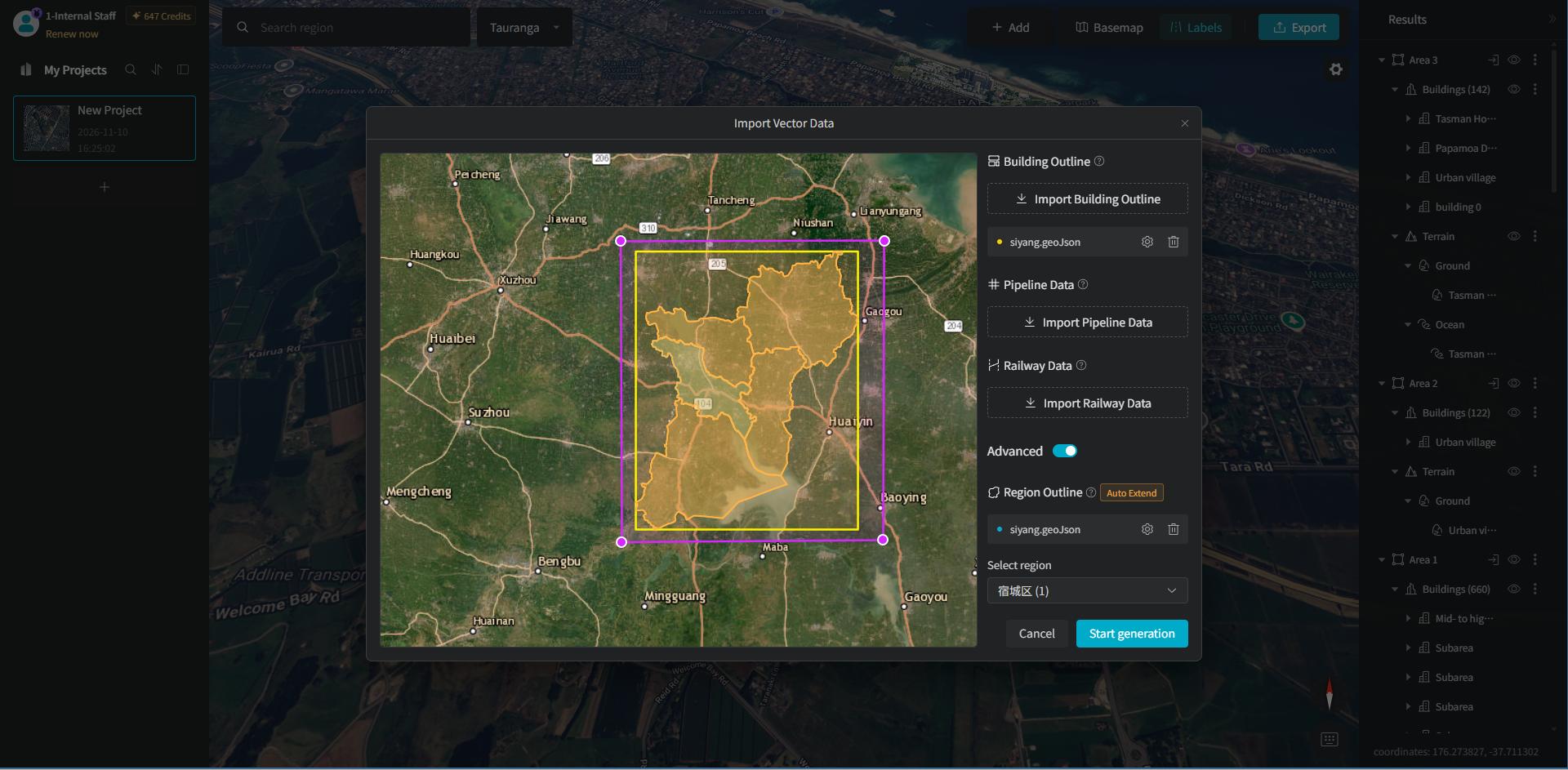
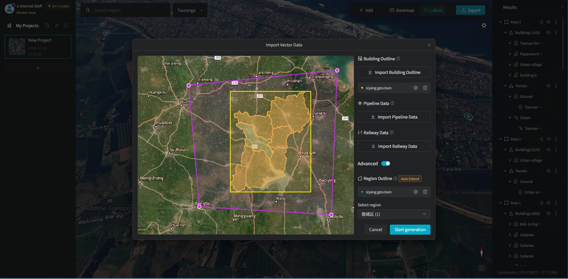
We can drag the endpoints or center points of the purple outer frame to enlarge or shrink the selection range.
3.3 Select an Area
If the area outline we import is relatively large — for example, a province or city area — we need to click the "Select Region" dropdown to choose the area to generate as needed.
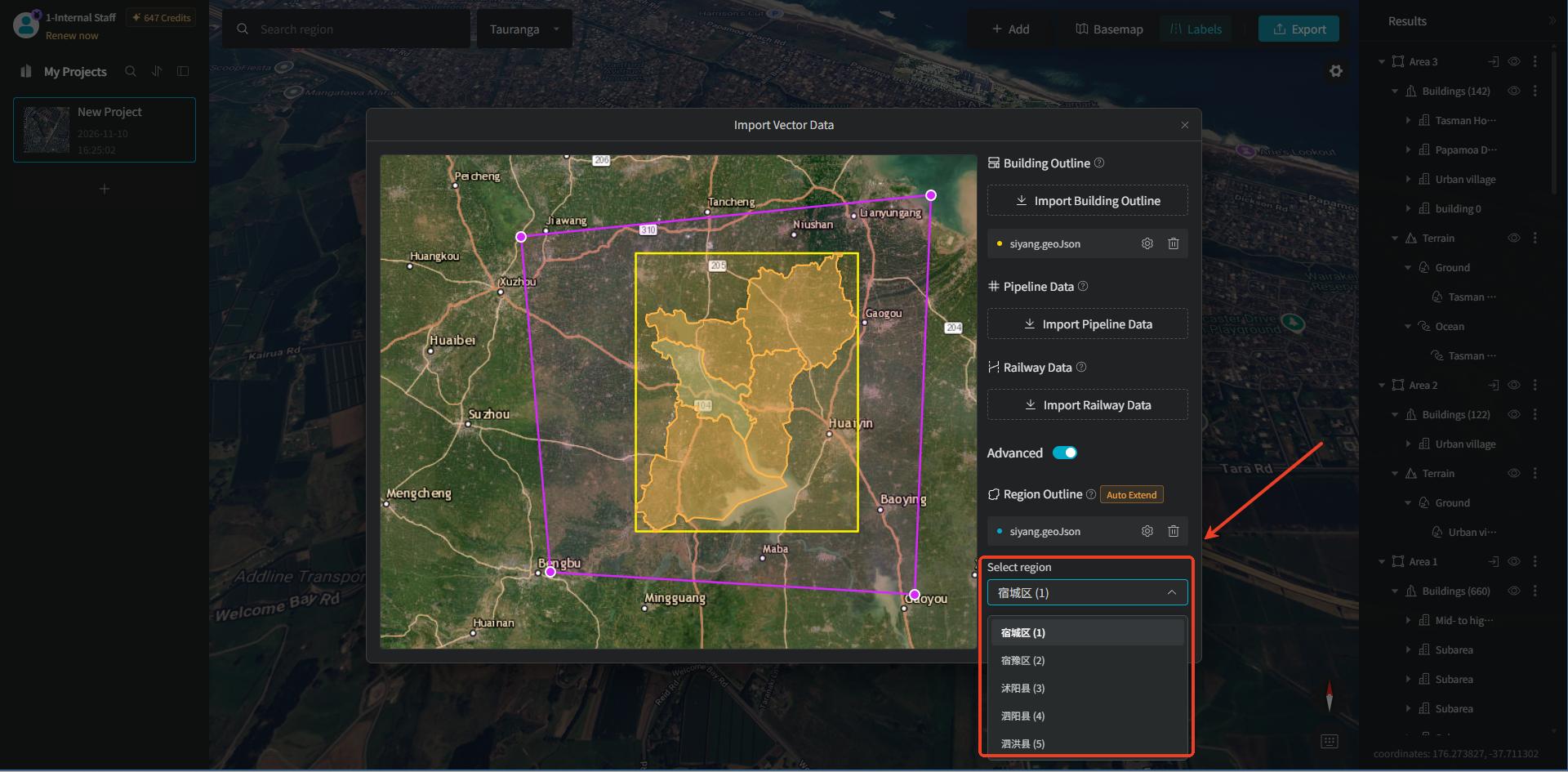
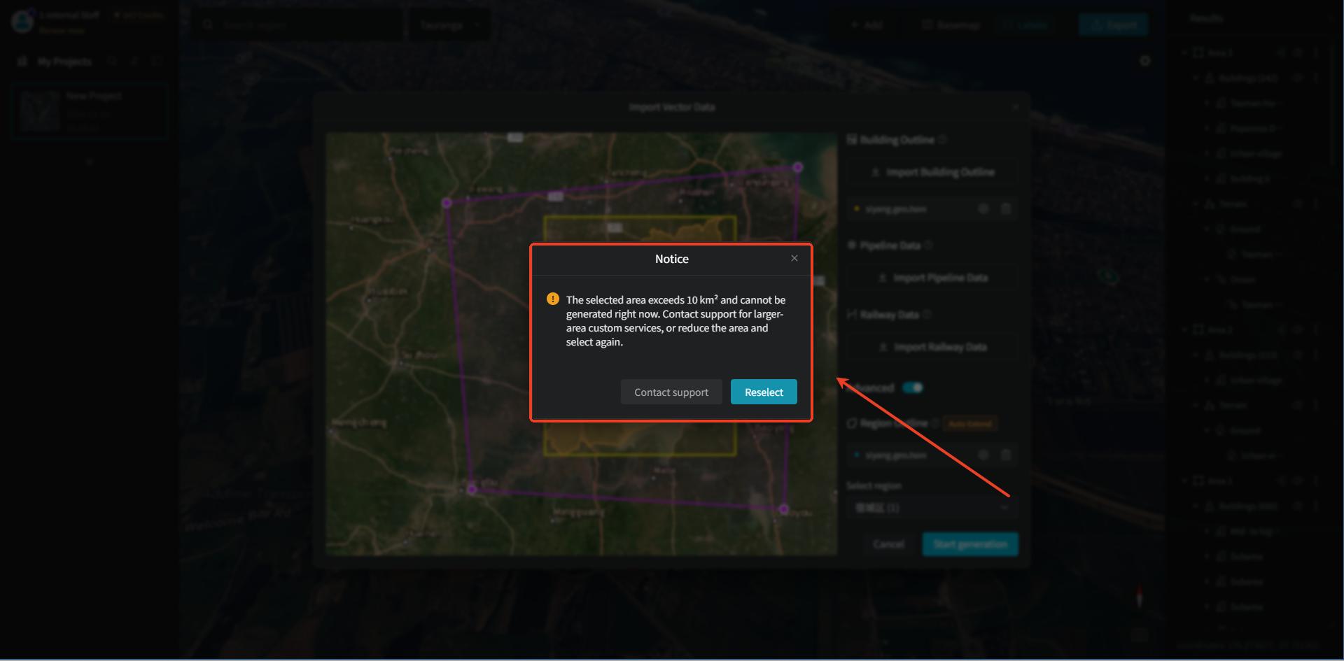
When the area of the selected region exceeds 10 km², generation is not supported. The dialog will prompt us to contact customer service to inquire about large-area customization services, or to narrow the range and select again.
4. Generate Building Models
After "Building Outline" and "Region Outline" are all imported, click "Start Generation," and AI will automatically recognize and generate the building models within the outlines.
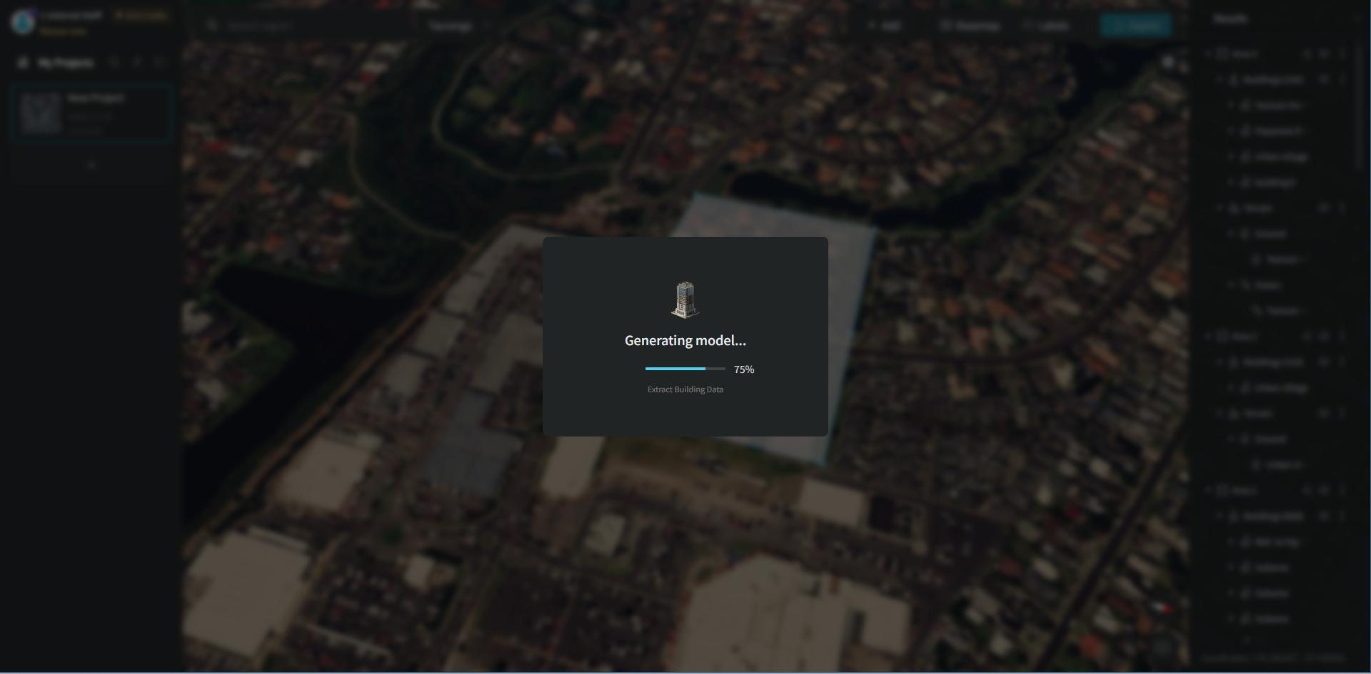
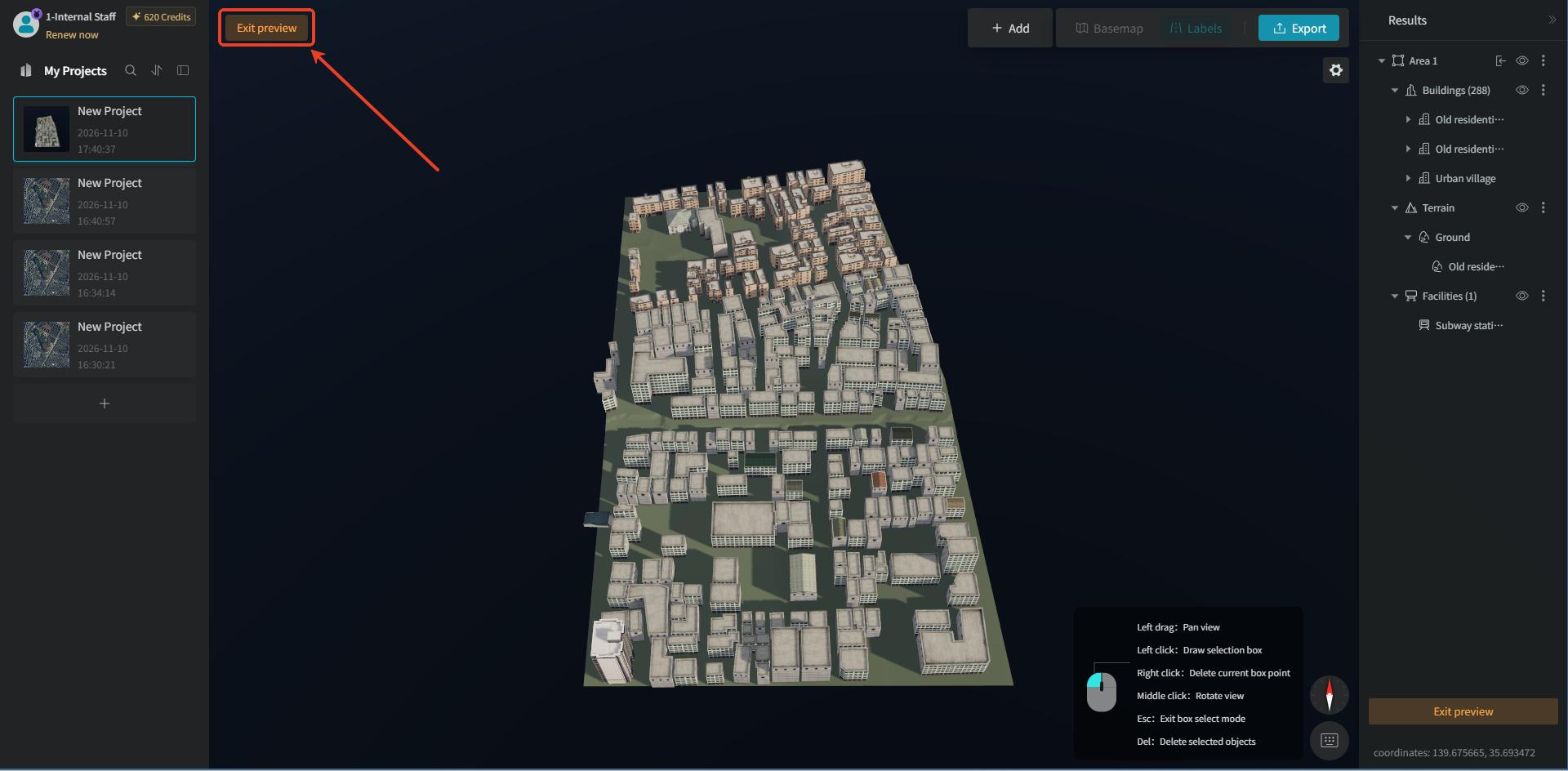
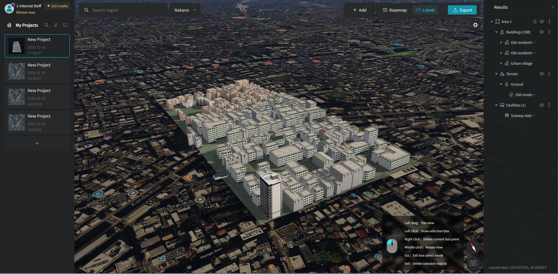
After the model is generated, you enter "Single-Building Preview" mode by default. Click the "Exit Preview" button in the top-left or bottom-right corner to return to the Earth preview mode, where you can preview on the map how the model blends with the surrounding environment.